Multi Temperaturecontroller KS800 KS800 PID PID PID PID KS800 PROFIBUS-DP PID PID PID PID KS800 Interface description KS800 PROFIBUS-DP 9499 040 50511 Valid from: 8395
SIMATIC® is a registered trademark of Siemens AG STEP® is a registered trademark of Siemens AG ® is a registered trademark of the PROFIBUS user organization (PNO) © PMA Prozeß- und Maschinen-Automation GmbH Printed in Germany All rights reserved. No part of this documentation may be reproduced or published in any form or by any means without prior written permission from the copyright owner.
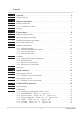
Contents 1 General . . . . . . . . . . . . . . . . . . . . . . . . . . . . . . . . . . 5 1.1 Scope of delivery . . . . . . . . . . . . . . . . . . . . . . . . . . . . . . . . . . . 6 2 Hints on operation. . . . . . . . . . . . . . . . . . . . . . . . . . . . 7 2.1 Interface connection . . . . . . . . . . . . . . . . . . . . . . . . . . . . . . . . . . 7 2.1.1 Installation of cables . . . . . . . . . . . . . . . . . . . . . . . . . . . . . . 7 2.2 Forcing . . . . . . . . . . . . . . . . . . . . . .
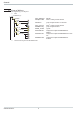
6 Function modules . . . . . . . . . . . . . . . . . . . . . . . . . . . 43 6.1 Function module for SIMATIC® S5 . . . . . . . . . . . . . . . . . . . . . . . . 43 6.1.1 6.1.2 6.2 Structure . . . . . . . . . . . . . . . . . . . . . . . . . . . . . . . . . . . 43 Function module call . . . . . . . . . . . . . . . . . . . . . . . . . . . . . 45 Function module for SIMATIC® S7 . . . . . . . . . . . . . . . . . . . . . . . . 46 6.2.1 Structure . . . . . . . . . . . . . . . . . . . . . . . . . . . . . . .
General 1 General The KS800 multi-temperature controller versions (9407-480-30001) are equipped with a PROFIBUS-DP interface for transmission of process parameter and configuration data. Connection is via the 9-pole sub-D connector socket. The serial communication interface permits connections to supervisory systems, visualization tools, etc. Another interface, which is always provided as standard, is the PC interface. This interface serves for connecting an engineering tool, which runs on a PC.
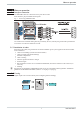
General 1.1 Scope of delivery The engineering set comprises: w Disk 3,5-Diskette (A:) Ks800dp Gsd S5_fb Example.fix S7_fb Example Type Example Pma_0800.gsd Pmadp1st.s5d GSD file STEP® 5-FB for parameter channel Pmadm3*.* project example in STEP® 5 for FixPoint Pma_parm.arj Ks800dmo.arj Ks800_1x.200 Demo308i.
Hints on operation 2 Hints on operation 2.1 Interface connection The PROFIBUS must be connected to the 9-pole sub-D socket. Serial interface, physical RS485-based signals. Fig.: 1 Connecting PROFIBUS-DP The construction of suitable cabling must be provided by the user, whereby the general cable specifications to EN 50170 vol.2 must be taken into account. 2.1.
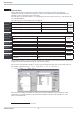
Process data 3 Process data During data transmission, distinction of process data to be transmitted cyclically and parameter / configuration data to be transmitted acyclically is made. The I/O data field is structured modularly for matching it to the requirements of the control task. Selection of the process data module is via configuration tools of the master circuits (e.g. with Siemens S5 via COM PROFIBUS).
Process data q Module A (process data of all 8 channels) No. Descr. Inputs 0 Unit_State 1 Xeff_1 2 Yeff_1 3 HC_1 4 Alarm_1 5 Status_1 6 Xeff_2 7 Yeff_2 8 HC_2 9 Alarm_2 10 Status_2 ... 36 Xeff_8 37 Yeff_8 38 HC_8 39 Alarm_8 40 Status_8 Outputs 41 Unit_Cntrl 42 Wvol_1 43 Yman_1 44 Cntrl_1 45 Wvol_2 46 Yman_2 47 Cntrl_2 ...
Process data Outputs 41 Unit_Cntrl 42 Wvol_1 43 Yman_1 44 Cntrl_1 45 Wvol_2 46 Yman_2 47 Cntrl_2 ... 63 Wvol_8 64 Yman_8 65 Cntrl_8 Inputs/outputs 66 Parameter channel W W W W W W W ] 52 4 2 2 2 2 2 2 23 60 60 21 60 60 21 32DA 1AA 1AA 16DA 1AA 1AA 16DA W W W 2 2 2 60 60 21 1AA 1AA 16DA R/W 8/8 F3 4AX D E E E q Module C (only parameter channels) No. Descr.
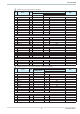
Process data q Module E (52 variable processdata and parameterchannel) No.. Descr.. R/W Number of Bytes ] 116 R 4 R 16 R 16 Inputs 0 Unit_State, Digital_Outputs 1 IN_1 … IN_8 2 IN_9 … IN_16 ... 6 IN_41 … IN_48 7 IN_49 … IN_52 Outputs 8 Unit_Cntrl I, Unit_Cntrl II 9 OUT_1 … OUT_8 10 OUT_9 … OUT_16 ...
Process data q Module H (Multiplexing of all 64 variable processdata and parameterchannel) No.. Descr. Inputs 0 Unit_State, Digital_Outputs 1 Index IN Read Write 2 Read Value Outputs 3 Unit_Cntrl I, Unit_Cntrl II 4 Index OUT 5 Write Value 6 Parameterchannel g FIX Point-Format Value Hex COM PROFIBUS R/W Number of Bytes ] 16 R 4 Read Write In- /Outputs 13 32DE R 2 50 1AE R 50 1AE W 2 ] 16 4 23 32DA W 2 60 1AA W 2 60 1AA R/W 8/8 F3 4AX Rem.
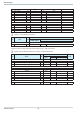
Process data Rem. B1 Alarm_x Bit no. D0 D1 D2 D3 D4 D5 D6 D7 Name Lim HH Lim H Lim L Lim LL Fail HCAl LeckAl do1_8Al MSB D7 D6 D5 D4 Allocation Alarm HH Alarm H Alarm L Alarm LL Alarm Sensor Fail Heating current alarm Leakage current alarm Alarm OUT1 ... 8 D3 D2 D1 Status ‘0’ off off off off no off off off LSB D0 Status ‘1’ on on on on yes on on on D2 D1 Status ‘0’ w external w no auto no off off LSB D0 Status ‘1’ W2 internal Wanf yes manual yes on on D2 LSB D0 Rem.
Process data Rem. E Unit_Contrl II MSB D31 Bit no. Name OUT17 D0 OUT18 D1 OUT19 D2 OstartG D3 OStopG D4 Dval D5 D6- D15 Rem. F Cntrl_x MSB D15 Bit no. Name A/M D0 Coff D1 w/W2 D2 We/w D3 OStart D4 OStop D5 D6 .. D15 Rem. G Digital_Outputs MSB D15 D14 D13 Bit-No. Name Y1_7 D0 Y2_7 D1 Y1_6 D2 Y2_6 D3 Y1_5 D4 Y2_5 D5 Y1_4 D6 Y2_4 D7 Y1_3 D8 Y2_3 D9 Y1_2 D10 Y2_2 D11 Y1_1 D12 Y2_1 D13 Y1_0 D14 Y2_0 D15 D30 D29 ... ...
Process data 3.2 Status and diagnosis messages For KS800 instrumwent status signalling, the external (user-specific) diagnosis must be used. The format corresponds to the instrument-related diagnosis (EN50170 volume 2 PROFIBUS). Instrument-specific diagnosis Octet 1 MSB D7 Bit no. D0 D1 D2 D3 D4 .. D7 D6 D5 D4 D3 D2 D1 Name Allocation Status ‘0’ Online/Conf On-line / configuration on-line DO1_12Fail Error do1 ... do12 no D=13_16Fail Error do13 ...
Process data 3.5 Parameter transmission For parameter transmission, the ‘parameter channel’ via which data can be exchanged transparently via the function block protocol is available. Thereby, all possible protocol access modes are supported (individual access, tens block and overall block). Communication to the controller is transparent, i.e. the user himself is responsible for monitoring ranges, operating modes (auto/hand) etc.
Process data 3.5.2 General communication structure For transmission of the parameters required for the function block protocol via an 8-byte data window, the access is composed of three parts: w Order header with specification of code, FB no., fct. no., type and the following real and integer values. Start telegram structure: Byte 0 Byte 1 Byte 2 Byte 3 Byte 4 ID ID1 Code FB no. Fct._no. Byte 5 Type Byte 6 Numb.real values Byte 7 Numb.
Process data 3.5.4 Data read procedure Start telegram: Master sends: Controller replies: Byte 0 0x10 Byte 1 ID1 Byte 2 Code Byte 3 Byte 4 Byte 5 FB no. Fct._no. Type Byte 0 Byte 1 0x10 Data telegrams: Byte 2 Byte 3 Byte 4 Byte 5 Byte 6 0 Byte 7 0 Byte 6 1) Numb. real values Byte 7 1) Numb. integer values Master sends: Byte 0 Byte 1 Byte 2 Byte 3 Byte 4 - 7 Controller replies: Byte 0 Byte 1 Byte 2 Byte 3 0x68 count 0x68 count Byte 4 - 7 Value Thereby, the first value is sent with Count = 1.
Process data Example 2: (message structure with data request) Reading the error code of self-tuning heating (MSG1) of controller (channel 2).
Process data The message structure with block accesses with code B2/B3 is shown using two examples below. The order of data to be transmitted is given in the relevant code table. Valid values for ID1: Configuration as FixPoint: 0, 1 Transmission of real values each as a FixPoint value Example 1: (message structure with data request) Reading set-point parameters (W0, W100, W2, Grw+, Grw- and Grw2) of controller (channel 7).
Process data 3.7 Data types Data values are classified in data types for transmission. w w FP Floating point number (Real) Range:as integer (in individual access) -9999 ... 0 ... 9999 as fix point-3000,0 ... 0,0 ... 3200,0 Exception:switch-off value ‘-32000’ INT positive integer number Range: 0 ... 32767 Range with configuration words: 0000 ... 9999 (Ä Page 27) Exception: Switch-off value ‘-32000’ w ST1 Status, bit-oriented, 1 byte Length Range: 00H ... 3FH, transmitted: 40H...
Quick entrance 4 Quick entrance The disk enclosed in the engineering set includes the GSD file, project examples for a SIMATIC® S5 / S7, the type file and configuration examples for COM PROFIBUS. Communication with a KS800-DP can be built up easily by means of the configuration and a project. 4.
Quick entrance After taking the test set-up into operation, testing of the I/O area and parameter channel call-up are possible by means of the graphic modules enclosed in the project. Graphic module 1: Shows all process data of channel 1 (fix point). Example: (specified set-point = 30) Value 300 is written in AW 4. Graphic module 2: Access to the function module parameters for parameter channel mapping is possible by means of this graphic module. Specify e.g.
Quick entrance 4.2 Quick entrance with S7 Test environment The following components are required for the test set-up: w Programming unit (PG740 recommended) w Automation unit - CPU315-2 DP w KS800-DP w Engineering set (order no. 9407 999 09x11) w Cable - PROFIBUS cable automation unit i KS800-DP - programming unit i automation unit 4.2.1 Example of a test environment: g A KS800-DP with address 5 shall be connected to a CPU315-2 DP via PROFIBUS-DP.
Quick entrance VAT 1: Shows the process data of all channels (fix point). Only channel 1 can be seen in the figure opposite. Example channel 1: (set-point specification = 30 output variable = 40 % manual operation) VAT 2: Access to the function module parameters for parameter channel mapping is possible by means of this variable table. Specify e.g.
Function block protocol 5 Function block protocol 5.1 Data structuring Due to the variety of information to be processed in KS800, logically related data and actions are grouped into function blocks. A function block has input data, output data, parameters and configuration data. 25 function blocks are defined for KS800. They are addressed via fixed block addresses (FB no.). Each block is also grouped in individual functions. Functions are addressed via function numbers (fct. no.).
Function block protocol 5.2 CODE tables 5.2.1 Structure of configuration words (C.xxxx) The configuration words given in the following code tables comprise several partial components, which can be transmitted only in common. The data in the table must be interpreted as follows: Example (C100): Code 71 Descr. R/W Type C100 R/W INT Description Range CFunc: Controller function (T,H) 0..xx0z WFunc:Set-point function (E) Description CFunc WFunc Thousands Hundreds Ones x x z Range 00 ... 07 0...
Function block protocol Rem. A Unit_State1 MSB D7 Bit no. D0 D1 D2...D4 D5 D6 D7 Name ‘0’ CNF ‘0’ UPD ‘1’ D6 D5 D4 D3 D2 Allocation always ‘0’ Instrument status always ‘0’ Parameter update always ‘1’ Parity LSB D0 D1 Status ‘0’ Status ‘1’ online configuration no yes Rem. B DPErr MSB D15 D14 D13 D12 D11 D10 D9 Bit no. Name D0 D1 D2 D3 D4...D15 Rem.
Function block protocol I/O connection Code Descr. R/W 0 Block 1...2 R 1 State_alarm_out R 2 State_dio R 20 Block 21...24 R 21 SnOEMOpt R 22 SnFabMonth R 23 SnCntHi R 24 SncntLo R 30 Block 31...33 R 31 Fdo1 R/W 32 Fdo2 R/W 33 Fdo3 R/W Rem. H State_alarm_out MSB D7 Bit no. Name R1 D0 R2 D1 R3 D2 do1_12 AL D3 HCscAL D4 ‘0’ D5 ‘1’ D6 D7 Rem. I State_dio Name Par_Nr w/w2 Coff Leck ‘0’ do13_16f ‘1’ D6 (function no.: 2) Range Rem.
Function block protocol GProcessVal Code Descr.. B2 Xeff Yeff HC Xeff Yeff HC ... Xeff Yeff HC State_alarm_out State_alarm_out ... State_alarm_out GProcessPar Code Descr.. B2 Wvol W2 Yman Wboost Tboost Wvol W2 Yman Wboost Tboost ... Wvol W2 Yman Wboost Tboost 9499 040 50511 (Funktions-Nr: 10) Range Rem.
Function block protocol GControlPar Code Descr. B2 A/M Coff w/W2 Ostart SoftStartEnable BoostStartEnable A/M Coff w/W2 Ostart SoftStartEnable BoostStartEnable ... A/M Coff w/W2 Ostart SoftStartEnable BoostStartEnable GAlarmPar Code Descr. B2 LimL LimH LimLL LimHH LimL LimH LimLL LimHH ...
Function block protocol GPIDPar Code Descr. B2 Xp1 Tn1 Tv1 T1 Xp1 Tn1 Tv1 T1 ... Xp1 Tn1 Tv1 T1 Channel 1 1 1 1 2 2 2 2 R/W R/W R/W R/W R/W R/W R/W R/W R/W Type INT INT INT INT INT INT INT INT Description Proportional band of channel 1 Integral time of channel 1 Derivative time of channel 1 min. cycle time of channel 1 Proportional band of channel 2 Integral time of channel 2 Derivative time of channel 2 min.
Function block protocol 5.2.3 Special accesses (FB no.: 10 ... 17 type no.: 10) Alternatively, access to the KS800 data is possible via function block ‘Special accesses’ . In this case, access is only via code B2. ProcessVal Code Descr. B2 Xeff Yeff HC State_alarm_out ProcessPar Code Descr. B2 Wvol W2 Yman Wboost Tboost ControlPar Code Descr. B2 A/M Coff w/W2 Osart SoftStartEnable BoostStartEnable AlarmPar Code Descr. B2 LimL LimH LimLL LimHH PIDPar Code Descr.
Function block protocol 5.2.4 Freely configurable (FB no.: 20 ... 27 type no.: 20) Function block ”Freely definable” defines data, which can be read only by block access 20 or 30. The ComWrite data can also be changed by mean of keys 31 – 38. Additionally, this Profibus interface setting provides the values for the relevant data modules. ComRead Code 20 21 22 23 24 25 26 27 28 Descr. Block Val 1 Val 2 Val 3 Val 4 Val 5 Val 6 Val 7 Val 8 ComWrite Code 30 31 32 33 34 35 36 37 38 Descr.
Function block protocol Parameter- a. Configuration-Data ComRead Code B2 41 42 43 44 45 46 47 48 49 51 52 53 54 55 56 57 Descr. ComReadBlock1 ComReadFctKey1 ComReadBlock1 ComReadFctKey1 ComReadBlock1 ComReadFctKey1 ComReadBlock1 ComReadFctKey1 ComReadBlock1 ComReadFctKey1 ComReadBlock1 ComReadFctKey1 ComReadBlock1 ComReadFctKey1 ComReadBlock1 ComReadFctKey1 Code B2 41 42 43 44 45 46 47 48 49 51 52 53 54 55 56 57 Descr.
Function block protocol 5.2.5 INPUT (FB no.: 60 ... 67 Type no.: 112) All data which concern acquisition and processing of all input values (analog/digital) are grouped in function block ‘INPUT’. The data are available once per controller channel. Process data General Code 00 1 3 10 13 18 Descr.
Function block protocol 5.2.6 CONTR (FB no.: 50 ... 57 Type no.: 91) All data which concern the controller are grouped in function block ‘CONTR’. They are available once for each controller channel. Process data General Code Descr. R/W Type Description 00 Block R Block Block access (1...9) 1 Status 1 R ST1 Status 1 3 W R FP Eff. set-point 4 X R FP Eff. process value 5 Y R FP Effective output value 6 xw R FP Control deviation 13 Status Alarm x R INT Status x and Alarm x 18 Type R INT Type no.
Function block protocol Rem. B2 Cntrl_x: (Code 39) MSB D15 D14 D13 D12 D11 D10 D9 Bit no. D0 D1 D2 D3 D4 D5 D6...D15 Name A/M Coff w/w2 we/wi OStart Ostop "0" Set-point Code 00 01 03 30 31 32 Rem. C Bit no. D0 D1 D2 D3 D4 D5 D6 D7 Descr. R/W Block R WState R Wint R Block R Wnvol R/W Wvol R/W WState: (code 01) MSB D7 D6 Name w/w2 we/wi w/wanf GRW Weff_fail ‘0’ ‘1’ Code 00 1 3 30 31 32 33 34 35 36 37 38 39 9499 040 50511 Descr.
Function block protocol Rem. D Status 1 Tuning ‘State_Tune1’ Bit no. D0 D1 D2 D3...D5 D6 D7 Name OStab Orun Oerr ‘0’ ‘1’ MSB D7 D6 D5 D4 Allocation Process at rest Optimization run Optimization result always ‘0’ always ‘1’ Parity D3 D2 Status ‘0’ no off Ok D1 LSB D0 Status ‘1’ yes on error Parameter a. configuration data General Code Descr. B3 71 C100 72 C101 73 C700 74 C180 Set-point Code B2 41 42 43 44 45 46 Descr. W0 W100 W2 Grw+ GrwGrw2 Algo Code B2 41 42 43 44 45 46 47 48 Descr.
Function block protocol Output variable Code B2 41 42 43 44 45 Descr. Ymin Ymax Y0 Yh LYh Tuning Code B2 41 42 43 44 45 Descr. YOptm dYopt POpt OXsd Trig1 Paramset x Code B2 41 42 43 44 45 46 47 48 Descr. Xp1 Tn1 Tv1 T1 Xp2 Tn2 Tv2 T2 R/W R/W R/W R/W R/W R/W R/W R/W R/W R/W R/W R/W R/W R/W R/W R/W R/W R/W R/W R/W R/W Start-up circuit Code B2 41 42 43 9499 040 50511 Descr.
Function block protocol 5.2.7 ALARM (FB no.: 70 ... 77 Type no.: 46) Function block ‘ALARM’ defines the overall alarm processing of the relevant controller. The data are available once per controller. Process data General Code 00 1 2 3 18 Descr. Block Status_Al1 Status_Al2 HC Type R/W R R R R R Type Block ST1 ST1 FP INT Description Block access (1 .. 3) Alarm status 1 Heating current alarm Heating current meas. value Type no. of function block Rem A Status_Al1 MSB D7 D6 D5 Bit no.
Function block protocol Parameter a. configuration data General Code B2 41 42 43 44 45 46 B3 71 72 Descr. LimL LimH xsd1 LimLL LimHH LimHC C600 R/W R/W R/W R/W R/W R/W R/W R/W Type FP FP FP FP FP FP INT C601 R/W INT Descr. LimL LimH xsd1 LimLL LimHH LimHC C600 R/W R/W R/W R/W R/W R/W R/W R/W Type FP FP FP FP FP FP INT C601 R/W INT General Code B2 41 42 43 44 45 46 B3 71 72 General Code B2 41 42 43 44 45 46 B3 71 72 Descr.
Function modules 6 Function modules 6.1 Function module for SIMATIC® S5 Function module FB206 serves for easy access to the controller parameter and configuration data (in P area). 6.1.
Function modules FB296 / FB207 A-A E-A DB-S DWAS DWLR ... ANZW DB25 DW 0 ... DW3 DW4 ... DW7 DW8 ... DW10 DW11 ... DW14 DW15 ... DW24 DB-S: 25 Provisional marker Management call1 1. DWAS: 4 Data set 1 3 words user data Management call2 2. DWAS: 11 Data set 2 10 words user data w DWLR (real), DWLI (integer) These parameters contain the relevant number of received data after a read access. With a write access, the number of data to be transmitted is specified.
Function modules w FBNR. (function block number) A function block is addressed by means of a function block number. This function block number can be within ‘0’ and ‘250’. Function block number ranges: 0 general data for the overall instrument 1 - 99 fixed function blocks w FKTNR (function number) A function as a partial address of a function block is also addressed with a function number. This function number can be within ‘0’ and ‘99’.
Function modules 6.2 Function module for SIMATIC® S7 The S7-FB handling principle corresponds to the S5 variant. When starting an order and as long as the order is active, calling up the FB is indispensable. Dependent of S7-CPU and DP-Master, the I/O handling is different. With a CPU315-2 DP with on-board DP interface, SFC modules 14 and 15 must be used for consistent data transmission. SFC modules 14 and 15 copy the I/O areas into the marker or data module area.
Function modules w Service This parameter determines the access type (write / read) Ä ID1. Write access: F0 = Integer Read access: F1 = Real Individual access 0 1 = = Integer Real This access (code xx) can be used for reading or writing an individual value of a function.
Function modules w the relevant number of data to be transmitted is filled in. DWLC is not required in KS800, value must be set to 0. ANZW This display word represents the current transmission status. Bit 4 can be used as an input for resetting the FB 206 / FB 207.
Annex 7 Annex 7.1 Terms COM PROFIBUS FB Fkt ET Function Function block GSD file HW ISO1745 PC-interface PCI PCI protocol PNO PROFIBUS-DP RS422 RS485 S5 / S7 Serial interface SW Type file Configuration tool (formerly COM ET200) of the Siemens company for PROFIBUS Abbr. f. function block Abbr. f. function Abbr. f. Engineering Tool a self-contained partial function of a function block seen from the interface self-contained processing unit Device-Database-File Abbr. f.
Annex MaxTsdr_6M = 450 MaxTsdr_12M = 800 Redundancy = 0 ; not supported Repeater_Ctrl_Sig = 2 ; TTL 24V_Pins = 0 ; not available ; ;—DP-Slave related key words——; Freeze_Mode_supp = 1 ; supported Sync_Mode_supp = 1 ; supported Auto_Baud_supp = 1 Set_Slave_Add_supp = 0 User_Prm_Data_Len = 0 ; no user prm data ;minimum slave poll cycle (Basis 100us): Min_Slave_Intervall = 1 Modular_Station = 1 ; modular device Max_Module = 0x01 ; max.
Annex EndModule ; ; 4. As process data B in compact form Module = “D: Compact Process data(8) + parameter” 0x11,\ 0x53, 0x53, 0x53, 0x53, 0x53, 0x53, 0x53, 0x53,\ 0x23,\ 0x62, 0x62, 0x62, 0x62, 0x62, 0x62, 0x62, 0x62,\ 0xF3 EndModule ; 5. Process data for 52 Variable data + parameter channel Module = “E: 52 Variable data + parameter” 0x13,\ 0x57, 0x57, 0x57, 0x57, 0x57, 0x57, 0x53,\ 0x23,\ 0x67, 0x67, 0x67, 0x67, 0x67, 0x67, 0x63,\ 0xF3 EndModule ; ; 6.
Subject to alterations without notice. © PMA Prozeß- und Maschinen-Automation GmbH Bei Änderungen erfolgt keine Mitteilung. Postfach 310 229, D - 34058 Kassel Modifications sans avertissement réservées.