©PMA Prozeß- und Maschinen-Automation GmbH 2004. Printed in Germany All rights reserved. No part of this document may be reproduced or published in any form or by any means without prior written permission by the copyright owner. A publication of PMA Prozeß- und Maschinen-Automation GmbH Subject to change without notice. PMA Prozeß- und Maschinen-Automation GmbH P.O.
Multi-Temperature-Controller KS 800 Contents 1 Safety hints . . . . . . . . . . . . . . . . . . . . . . . . . . . . . . . . . . . . . . . . . . . . . . . . . . . . . . . 1.1 Electromagnetic compatibility . . . . . . . . . . . . . . . . . . . . . . . . . . . . . . . . . . . . . . 5 5 2 General . . . . . . . . . . . . . . . . . . . . . . . . . . . . . . . . . . . . . . . . . . . . . . . . . . . . . . . . . . 2.1 Versions . . . . . . . . . . . . . . . . . . . . . . . . . . . . . . . . . . . . . . . . . . .
Multi-Temperature-Controller KS 800 9 Indicator LEDs . . . . . . . . . . . . . . . . . . . . . . . . . . . . . . . . . . . . . . . . . . . . . . . . . . . . 9.1 Outputs . . . . . . . . . . . . . . . . . . . . . . . . . . . . . . . . . . . . . . . . . . . . . . . . . . . . . 9.2 PWR, COM and alarm indicator LED . . . . . . . . . . . . . . . . . . . . . . . . . . . . . . . 27 27 27 10 Maintenance and measures in case of trouble 10.1 Cleaning . . . . . . . . . . . . . . . . . . . . . . . . 10.
Multi-Temperature-Controller KS 800 1 Safety hints Following the enclosed safety hints 9499 047 07101 is indispensable! For hints on the power supply to be used, see section 4.3 Supply voltage 1.1 Electromagnetic compatibility The unit conforms to European guideline 89/336/EEC and is provided with the CE marking.
Multi-Temperature-Controller KS 800 2 General KS 800 is a microcomputer-based multi-loop temperature controller. Functions "set-point lowering" and "heating/cooling with four alarms" make it ideally suited for temperature control of plastics 20 processing machinery, moulds, packaging machinery, tempering units and similar thermal processes. Furthermore, with high-power heating elements (e.g.
Multi-Temperature-Controller KS 800 2.1.
Multi-Temperature-Controller KS 800 Several units: For mounting several units side by side, snap on the first unit to the rail and lock only the side on which no other unit shall be mounted. Snap on the second unit like the first one, approx. 2 cm beside the first unit and shift it sideways to connect it to the first unit (locking pins click into position). Press down the second latch of the first unit only now.
Multi-Temperature-Controller KS 800 4 Electrical connection • Measurement and signal leads may carry max. 50 V rms against earth. • Mains cables must be kept separate from signal and measurement cables. • For protection of the outputs and avoiding interference, connected final elements must be fitted with protective circuits according to manufacturer specification. 4.1 Terminals All terminals leading to the process are designed as (plug-in) screw terminals or spring clamps.
Multi-Temperature-Controller KS 800 For units with analog outputs, 2 x 8-pole terminal, order no. 231-308/026-000, resp. 9463 000 05321 is required additionally. 4.2 Bus-Stecker For connecting KS 800 to the fieldbus system, the connectors listed in the table must be used: Profibus z.B.
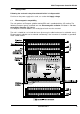
Multi-Temperature-Controller KS 800 4.3 Galvanic isolations The galvanic isolations of KS 800 are shown in the following diagram. Identical block shading means that blocks are galvanically connected. I.e. all outputs are galvanically connected, but isolated from inputs and microcontroller (controller). All inputs are also galvanically connected. An exception are the digital inputs/outputs, which are connected with controller outputs (and supply voltage) independent of their configuration.
Multi-Temperature-Controller KS 800 4.4 Supply voltage KS 800 is designed for a supply voltage rating of 24V DC, range The supply voltage must comply with the conditions of protective IEC 364-4-41 [VDE 0100-410]. Power supply load by one KS 800: 8 controller outputs + 4 alarm outputs each with 0,07A plus controller consumption results in a max. overall load (at 24V) of approx. 18V to 30V, residual ripple 5%.
Multi-Temperature-Controller KS 800 5 Inputs (A complete KS 800 connecting diagram is given in section 7.) Examples for connection are given in section 5.7. The following rules are applicable to all analog inputs: Unused analog inputs must be short-circuited! Thermocouple and DC voltage: Connect + and - terminal of each input. Resistance thermometer: Unused inputs for resistance thermometers must be configured as mV or ther mocouple input.
Multi-Temperature-Controller KS 800 The controller inputs are not galvanically isolated. Therefore, measurement errors may occur with thermocouple measurements above approx. 700°C and unsuitable thermocouples. This effect is due to a decrease of the insulation value between protective tube and thermocouple to values of a few kOhm from these temperatures dependent of construction type and insulation material.
Multi-Temperature-Controller KS 800 5.3 Resistance thermometer (IN1+/IN1-/IPT1 ... IN8+/IN8-/IPT8) Pt 100, 2 or 3-wire connection Resistance thermometer type PT 100 to DIN/IEC 751 can be connected in 2 or 3-wire circuit. The max. measuring range is -100,0 ... 850,0°C, temperature-linear. Connection in 3-wire circuit is possible without lead resistance adjustment, provided that the crosssection of the individual wires is identical.
Multi-Temperature-Controller KS 800 The current transformer input is not a measurement input in the sense of a calibrated measuring instrument. The software for display calculation is designed for a single-phase 1000:1 current transformer (30A = 30mA). When applying other values to this input, there will be an error (3-phase transformers, wave-form factor due to rectification and internal resistance outside KS 800...). Nevertheless, applying other variables to this input, e.g.
Multi-Temperature-Controller KS 800 5.6 Input circuit examples 5.7 Digital inputs KS 800 contains 4 digital inputs, which can also be configured individually as inputs, unless required as controller outputs (cooling output with three-point controllers or closed output with three-point stepping controllers). The inputs are "high-active" and designed as current sink according to IEC 1131 type 1. The current requirement is approx. 5 mA. Logic "0" = -3...5 V Logic "1" = 15...
Multi-Temperature-Controller KS 800 5.8 Input/output forcing Unless connections IN/OUT13...IN/OUT16 or OUT17...OUT19 are used for their actual tasks, they can be used as "free digital inputs/outputs" of a supervisory system. In this case, they cannot be influenced by KS 800, but only as a system component via the system bus. Inputs/outputs IN/OUT13...IN/OUT16 can be configured as digital inputs or outputs. Alarm outputs OUT17...
Multi-Temperature-Controller KS 800 6 Outputs (For the complete connecting diagram, see section 7.2, 7.3) 6.1 Controller outputs: Dependent of controller configuration, various output functions are possible: 2-pnt. controller signaller 1 output 1) 3-pnt. controller signaller 2 outputs 2) 3-pnt. stepping controller OUT 1 heating (contr. 1) heating (contr. 1) open (contr. 1) OUT 2 heating (contr. 2) heating (contr. 2) open (contr. 2) OUT 3 heating (contr. 3) heating (contr. 3) open (contr.
Multi-Temperature-Controller KS 800 OUT17...OUT19 3 outputs for alarms. The alarm allocation to the three outputs is configurable. Unused outputs cannot be switched off individually. These outputs go to the status which is defined in the KS 800 configuration. The inputs of these unused controllers must be short-circuited (see also section 5). Because of the variety of KS 800 configurations, note that: The KS 800 options can be limited by the controller configuration.
Multi-Temperature-Controller KS 800 Starting with controller 1, the 1st controller, which has a continuous output, is allocated to analog output 1 (AO1). E.g. controller 1 and 2 are two-point controllers (heating, switching), controller 3 is configured as a three-point controller (heating switching, cooling continuous): the first free analog output (AO1) is allocated to the cooling output of controller 3. (The output of the 3rd controller is connected with the 1st analog output (AO1).
Multi-Temperature-Controller KS 800 Note: Unless these alarm outputs are used as alarm outputs, they can also be used as digital outputs of a control system (see also section 5.8). 6.4 Constant voltage and auxiliary relays KS 800 version 9407 480 xx3xx is provided with a constant voltage source, which is galvanically isolated from all other KS 800 inputs and outputs. This constant voltage source can be used for energizing a strain-gauge bridge (pressure sensor).
Multi-Temperature-Controller KS 800 7 Circuit diagrams 7.1 Input/output circuit diagram For better understanding with complex connecting problems, the circuit diagrams of inputs and outputs are shown below.
Multi-Temperature-Controller KS 800 7.
Multi-Temperature-Controller KS 800 7.
Multi-Temperature-Controller KS 800 8 Digital interfaces Communication with controller KS 800 is possible only via the digital interfaces. Reading process values, changing set-points or control parameters is always done via these interfaces. There are two types of interfaces: 8.1 Engineering tool interface The PC interface is provided on all controller versions. This interface is a special interface using the ISO 1745 protocol.
Multi-Temperature-Controller KS 800 8.2.2 DeviceNet adaptor If KS 800 is operated with DeviceNet, an adapter is required for this bus system. This adaptor is available under order number 9407-799-00301.
Multi-Temperature-Controller KS 800 8.2.3 COM2 interface Address and Baudrate for the COM2 interface can be adjusted via hardware or software for each KS 800. Via hardware, the address is adjustable within ”01” and ”99”. In position ”00”, the address stored in EEPROM which can be changed via software will be used when switching on. Priority is given to the address adjusted via switch position. This address and baudrate cannot be readout or changed via software.
Multi-Temperature-Controller KS 800 8.3 Terminating resistors Hints related to baudrates, bus lengths, properties of electrical cables and mutual effects are given in the relevant interface descriptions. All KS 800 versions are delivered without terminating resistors at the bus connectors which must be plugged into the free bus connector of the last unit. The resistors required for each bus must be added externally to the last unit at both ends of the bus cable.
Multi-Temperature-Controller KS 800 LED on: O.K., cyclic data exchange busy LED blinks: (2 Hz) data communication interrupted LED blinks: (4 Hz) PROFIBUS parameter or configuration error AL1...AL3 30 With KS 800 configured for alarm functions, these LEDs are lit in case of the relevant alarm.
Multi-Temperature-Controller KS 800 10 Maintenance and measures in case of trouble The KS 800 multiple controller needs no particular maintenance. There are no parts in the unit which need preventive maintenance or care. 10.1 Cleaning If necessary, the aluminium and plastics components must be cleaned carefully with spirit. Do not use solvants or scouring agents. 10.
Subjekt to alteration without notice. Printed in Germany 9499 040 49111 (022004) © PMA Prozeß- und Maschinen-Automation GmbH P.O.B.