PMA Prozeß- und Maschinen-Automation GmbH Multi-temperature controller KS 800 KS800 PID PID ISO 1745 KS800 PID PID PID PID PID PID KS800 Interface description S800 ISO 1745 protocol 9499 040 49411 valid from: 8357
© PMA Prozeß- und Maschinen-Automation GmbH 1999 Printed in Germany (9909) All rights reserved. No part of this document may be reproduced or published in any form or by any means without prior written permission from the copyright owner. A publication of PMA Prozeß- und Maschinen Automation P.O. Box 310229 D.
Inhalt 1 Hints on operation. . . . . . . . . . . . . . . . . . . . . . . . . . . . 5 1.1 Connecting the interface . . . . . . . . . . . . . . . . . . . . . . . . . . . . . . . . 5 2 Interface protocol . . . . . . . . . . . . . . . . . . . . . . . . . . . . 6 2.1 Protocol layer 1 . . . . . . . . . . . . . . . . . . . . . . . . . . . . . . . . . . . . 6 2.1.1 2.1.2 2.1.3 2.1.4 2.2 Data format Baud rate . . Parity . . . . Addressing . . . . . . . . . . . . . . . . . . . . . . . . . . . . . . .
7 Annex . . . . . . . . . . . . . . . . . . . . . . . . . . . . . . . . . . 31 7.1 Terms . . . . . . . . . . . . . . . . . . . . . . . . . . . . . . . . . . . . . . . . . 31 8 Index . . . . . . . . . . . . . . . . . . . . . . . . . . . . . . . . . .
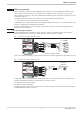
Hints on operation 1 Hints on operation Multi-temperature controller version KS800-RS is provided with a serial, bussable RS485 interface which can be used for transmission of process, parameter and configuration data. Connection is via (a) 9-pole sub-D socket(s)(connector(s)). The serial communication interface permits connections to supervisory PLCs, visualization tools, etc. An RS485/422 hardware interface is realized.
Interface protocol 2 Interface protocol 2.1 Protocol layer 1 Bus connection is physical: w w via the PC interface as a TTL signal (COM 1) via an RS485/422 connection (COM 2) with version KS800-RS. 2.1.1 Data format The following transmission format, fixed, must be used: w 1 start bit, w 7 bits ASCII value or 7 bits binary w 1 parity bit (EVEN) w 1 stop bit LSB is transmitted first, MSB is parity bit. 2.1.2 Baud rate The Baud rate for the serial interface is adjustable.
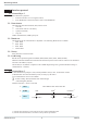
Interface protocol q for data request: RDR (Request Data with Reply) data request with reply in one message cycle. Data flow direction : KS800 r Master a) Master EOT
ENQ b) KS800 STX ETX BCC c) Master EOT or continue with a NAK 1) repeat a, (1) or EOT no reaction 2) after timeout: (2) EOT or continue with a 2.2.Message structure 3 Message structure 3.1 Message elements In the following section, some expressions which shall be explained as follows are used: Element Description Address of a participating unit, always 2 bytes long, adjustable on the instruments Data field composed of a) fields a.
Message structure Bem. E Addition selection criteria In order to form a purposeful sub-set from the variety of data, additional selection criteria are defined: q Function block number A function block is addressed by a function block number. It is within ‘0’ and ‘250’ and is appended to the code field by means of a comma.‘,
Message structure 3.3 Data types Data values are classified according to data types for transmission. Only characters which can be represented in ASCII are permitted. w BCD Floating Point number in BCD-ASCII format, Range: -9999 ... -0.001, 0, 0.001 ... 9999 optional: negative polarity sign and decimal point permitted; exponent representation not permitted. KS800 controllers with an accuracy of max. 4 digits.
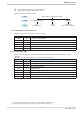
Standard protocol 4 Standard protocol The KS800 standard protocol version represents instrument-specific standard data. 4.1 CODE table Code 18 80 81 82 83 Bem. A Bem. B Description System ident Block 81... 83 Write Error Write Error Position Read Error R/W R R R R R Type SYS16 Block INT INT INT Range Description System identification 0, 100 ... 127 Error of last write access 0 ... 99 Position of last write access error 0, 100 ... 127 Error of last read access Rem.
Standard protocol Err. no.
Function block protocol 5 Function block protocol 5.1 Data structure Due to the variety of information to be processed in KS800, logically related data and actions are grouped in function blocks. A function block has input, output data, parameters and configuration data. For KS800, 25 function blocks are defined. They are all addressed via fixed block addresses (FB no.). Each block is also divided into several functions. Functions are addressed via function numbers (Fct-no.).
Function block protocol 5.2 CODE tables 5.2.1 Structure of configuration words (C.xxxx) The configuration words mentioned in the following code tables are composed of several sections, which can be transmitted only in common. The data in the table must be interpreted as follows: Example (C100): Code 71 Descr. R/W Type C100 R/W INT Description Range g Description CFunc: Controller function Wfunc: set-point function CFunc Thousands Hundreds x x 00 ...
Function block protocol Bem. A Unit_State1 MSB D7 Bit no. D0 D1 D2...D4 D5 D6 D7 Bem. B D5 Name ‘0’ CNF ‘0’ UPD ‘1’ D4 D3 D2 Allocation Always ‘0’ Instrument status Always ‘0’ Parameter update Always ‘1’ Parity D14 D13 D12 Bit no. Name D0 D1 D2 D3 D4...
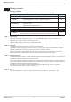
Function block protocol I/O connection Code 0 1 2 20 21 22 23 24 30 31 32 33 Bem. H Des. Block 1...2 State_alarm_out State_dio Block 21...24 SnOEMOpt SnFabMonth SnCntHi SncntLo Block 31...33 Fdo1 Fdo2 Fdo3 R/W R R R L L L L L L L/S L/S L/S Description Range (Function no.: 2) Rem. Status alarm outputs Status digital inputs/outputs G H Seriennummer OEM-Feld Seriennummer Fabrikationsmonat Seriennummer Zähler High Seriennummer Zähler Low Forced digitale Ausgänge: OUT1 ...
Function block protocol GProcessVal Code Bez. B2 Xeff Yeff HC Xeff Yeff HC ... Xeff Yeff HC State_alarm_out State_alarm_out ... State_alarm_out GProcessPar Code Bez. B2 Wvol W2 Yman Wboost Tboost Wvol W2 Yman Wboost Tboost ... Wvol W2 Yman Wboost Tboost (Funktions-Nr: 10) Bereich Bem.
Function block protocol GControlPar Code Bez. B2 A/M Coff w/W2 Ostart SoftStartEnable BoostStartEnable A/M Coff w/W2 Ostart SoftStartEnable BoostStartEnable ... A/M Coff w/W2 Ostart SoftStartEnable BoostStartEnable GAlarmPar Code Bez. B2 LimL LimH LimLL LimHH LimL LimH LimLL LimHH ...
Function block protocol GPIDPar Code Bez. B2 Xp1 Tn1 Tv1 T1 Xp1 Tn1 Tv1 T1 ...
Function block protocol 5.2.3 Sonderzugriffe (FB-Nr.: 10 ... 17 Typ-Nr.: 10) Der Funktionsblock ‘Sonderzugriffe’ ermöglicht, auf die Daten des KS800 in anderer Form zuzugreifen. Der Zugriff kann nur über den Code B2 ausgeführt werden. ProcessVal Code Bez. B2 Xeff Yeff HC State_alarm_out ProcessPar Code Bez. B2 Wvol W2 Yman Wboost Tboost ControlPar Code Bez. B2 A/M Coff w/W2 Osart SoftStartEnable BoostStartEnable AlarmPar Code Bez. B2 LimL LimH LimLL LimHH PIDPar Code Bez.
Function block protocol 5.2.4 Frei konfigurierbar (FB-Nr.: 20 ... 27 Typ-Nr.: 20) Der Funktionsblock “Frei konfigurierbar” definiert Daten die dann per Blockzugriff 20 bzw. 30 gelesen werden können. Die Daten des ComWrite können mit den Schlüsseln 31 - 38 auch geändert werden. Zusätzlich stellt diese Einstellung der Profibus-Schnittstelle für die entsprechenden Datenmodulen die Werte zur Verfügung. ComRead Code 20 21 22 23 24 25 26 27 28 Bez.
Function block protocol Parameter- u. Konfigurationsdaten Bem. B ComRead Code B2 41 42 43 44 45 46 47 48 49 51 52 53 54 55 56 57 Bez. ComReadBlock1 ComReadFctKey1 ComReadBlock1 ComReadFctKey1 ComReadBlock1 ComReadFctKey1 ComReadBlock1 ComReadFctKey1 ComReadBlock1 ComReadFctKey1 ComReadBlock1 ComReadFctKey1 ComReadBlock1 ComReadFctKey1 ComReadBlock1 ComReadFctKey1 Code B2 41 42 43 44 45 46 47 48 49 51 52 53 54 55 56 57 Bez.
Function block protocol 5.2.5 INPUT (FB no.: 60 ... 67 Type no.: 112) All data which concern acquisition and processing of all input values (analog/digital) are grouped in function block ‘INPUT’. The data are provided once per controller channel. Process data Code 00 1 3 10 13 18 Bem. A General Des. Block Input_x_Fail x1 Block INP1 Function Type R/W R R R R R R Type Block ST1 BCD Block BCD INT Statusbyte Input_X_Fail: MSB D7 D6 Bit no. Name INP1F D0 D1...
Function block protocol 5.2.6 CONTR (FB no.: 50 ... 57 Type no.: 91) All data concerning the controller are grouped in function block ‘CONTR’. They are provided once for each controller channel. Process data General Bem. A Code Des. 00 Block 1 Status 1 3 W 4 X 5 Y 6 xw 18 Type 20 Block 21 Xeff 22 Yeff 23 HC 24 Unit_State 25 Alarm_x 26 Status_x 30 Block 33 A/M 34 OStart 35 We/i 36 w/W2 38 Coff Status1: (code 01) Bit no. D0 D1 D2 D3 D4 D5 D6 D7 Set-point Bem. B Code Des.
Function block protocol Output variable Code 30 31 32 33 34 35 Code 00 1 3 30 31 32 33 34 35 36 37 38 39 Bem. C Des. Block dYman Yman Yinc Ydec Ygrw_ls R/W R R/W R/W R/W R/W R/W Tuning Des. Block State_Tune1 ParNeff Block ParNr Tu1 Vmax1 Kp1 MSG1 Tu2 Vmax2 Kp2 MSG2 Type Block BCD BCD INT INT INT R/W R R R R R/W R R R R R R R R Output variable processing Description Block access (31, 35) Difference output variable Absolute output variable Increment. output variable Decrement.
Function block protocol Code B2 Code B2 Code B2 Code B2 Code B2 Code B2 Set-point Des. W0 W100 W2 Grw+ GrwGrw2 41 42 43 44 45 46 Algo 41 42 43 44 45 46 47 48 Des. Xsh Tpuls Tm Xsd1 LW Xsd2 Xsh1 Xsh2 R/W R/W R/W R/W R/W R/W R/W R/W R/W R/W R/W R/W R/W R/W R/W R/W Output variable Des. Ymin Ymax Y0 Yh LYh 41 42 43 44 45 R/W R/W R/W R/W R/W R/W Tuning 41 42 43 44 45 Des. YOptm dYopt POpt OXsd Trig1 Paramset x 41 42 43 44 45 46 47 48 Des.
Function block protocol 5.2.7 ALARM (FB-Nr.: 70 ... 77 Typ-Nr.: 46) Function block ‘ALARM’ defines the overall alarm processing of the relevant controller. The data are provided once per controller channel. Process data General Code 00 1 2 3 18 Bem. A Des. Block Status_Al1 Status_Al2 HC Type Type Block ST1 ST1 BCD INT Description Block access (1 .. 3) Alarm status 1 Heating current alarm Heating current meas. value Type no. of function block Range Rem. A B 46 Status_Al1 Bit no.
Examples 6 Examples 6.1 Message examples in standard protocol Example: The computer requests system identification (code 18) from KS800 with address 01. Computer requests: EOT 0 1 KS 800 replies: STX 1 8 1 8 ENQ = 3 0 , 1 5 7 2 7 5 1 0 , 0 0 0 0 ETX BCC = 30 means a KS800 is concerned 15727510 = Software code no. 4012-157-27510 0000 = Order no. 9407-480-00001 6.
Examples 6.2.3 Block access (overall block) This access can be used for reading and writing all parameter (code B2) and configuration data (code B3) of a function. The following conditions are applicable for this access: w For writing data with ‘Code B3’, the unit must be switched to configuration mode (Ä see page 14 ‘OpMod’). All new configuration data and parameters entered are only effective, when the unit was switched back to on-line.
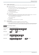
Examples 6.3 Message structure in function block protocol 6.3.1 INSTRUMENT Message structure for function ‘General’ Block access to configuration data max. eff. length: 41 bytes STX B3 , 0 , 0 = 0 , 0 , 5 , C900 , Adr1 , C904 , C902 , Adr2 ETX BCC Message structure for function ‘I/O connection’ Block access to configuration data max. eff. length: 43 bytes STX B3 , 0 , 2 = 0 , 1 , HC100 , 4 , C500 , C530 , C551 , HCcycl ETX BCC 6.3.
Annex 7 Annex 7.1 Terms FB Fkt ET Function Function block HW ISO1745 PC interface PCI PCI protocol RS422 RS485 SW TTL 990924 Abbr. of function block Abbr. of function Abbr. of Engineering Tool A self-contained partial function of the function block seen from the interface Self-contained processing unit Abbr. f.
Index 8 Index Neuer Index A Address field . . . . . . . . . . . . . . . . . . 8 Addressing . . . . . . . . . . . . . . . . . . . 6 B Baud rate . . . . . . . . . . . . . . . . . . . . 6 C Character format . . . . . . . . . . . . . . . . 7 Code . . . . . . . . . . . . . . . . . . . . . . . 8 D Data format . . . . . . . . . . . . . . . . . . . 6 Data request . . . . . . . . . . . . . . . . . . . 7 Data sending . . . . . . . . . . . . . . . . . . 6 F Function block number . . . . . . . . . . . . .
Subject to alterations without notice. © PMA Prozeß- und Maschinen-Automation GmbH Bei Änderungen erfolgt keine Mitteilung. Postfach 310 229, D - 34058 Kassel Modifications sans avertissement réservées.