©PMA Prozeß- und Maschinen-Automation GmbH. Printed in Germany All rights reserved. No part of this document may be reproduced or published in any form or by any means without prior written permission by the copyright owner. A publication of PMA Prozeß- und Maschinen-Automation GmbH Subject to change without notice. PMA Prozeß- und Maschinen-Automation GmbH P.O.
KS 800 CAN-Interface Contents 1 Introduction . . . . . . . . . . . . . . . . . . . . . . . . . . . . . . . . . . . . . . . . . . . . . . . . . . . . . . 5 2 Service data objects . . . . . . . . . . . . . . . . . . . . . . . . . . . . . . . . . . . . . . . . . . . . . . . . 7 3 Process data objects . . . . . . . . . . . . . . . . . . . . 3.1 Information Record (send PDO from KS800): 3.2 Control Record (KS800 receive PDO): . . . . 3.3 PDO transfer behaviour . . . . . . . . . . . . . . . 3.3.
KS 800 CAN-Interface 10 Application example . . . . . . . . . . . . . . . . . . . . . . . . . . . . . 10.1 KS800 standard settings . . . . . . . . . . . . . . . . . . . . . . 10.2 Adjusting a heating/cooling controller . . . . . . . . . . . . . 10.3 Adjusting a H/C controller and activating the self-tuning . . . . . . . . . . . . . . . . . . . . . . . . . . . . . . . . . . . . . . . . . . . . . . . . . . . . . . . . . . . . . . . . . . . . . . . . 40 40 40 41 11 CAN 11.1 11.2 11.3 11.
KS 800 CAN-Interface 1 Introduction Controller KS800 is provided with a CAN interface, via which all data (parameter and configuration data) required for operation can be sent to the controller. A master (PC or PLC) can also read all process data via this interface. According to "CANopen", the accesses are grouped into SDOs (Service Data Objects) and PDOs (Process Data Objects). SDOs are provided for configuration and parameter setting of bus units and PDOs are provided for the normal operating values.
KS 800 CAN-Interface Network management: For communication monitoring, KS800 offers the possibility of "nodeguarding", which enables the master to detect whether a KS800 is connected to the bus and whether the communication to the controller is ensured. Adjusting the node ID (node address) and CAN-baudrate required for identification of a CAN unit is done using the KS800 Engineering Tool via the diagnosis interface. Adjusting via CAN-Bus is also possible (see chapter 7).
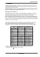
KS 800 CAN-Interface 2 Service data objects An SDO is logically determined to exactly two partners - 1 master and 1 slave. Simultaneous access to the KS800 by two different masters is not possible, since only one SDO channel is available for "tx" and for "rx". Max. 4 bytes of usable data can be transmitted by means of SDOs. The remaining 4 bytes are used as follows: 1 byte for the command: 2 bytes for the index: transmission mode object identification (e.g.
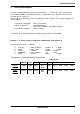
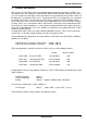
KS 800 CAN-Interface Example 2. A master reads a process value from a KS800 with node address 2: The message structure is as follows: ⇒ ⇒ ⇒ ⇒ COB_ID CMD INDEX SUBINDEX = = = = SDO at node 2 read access process value e.g. controller 3 = = = = 0x600 + 2 0x40 0x2202 03 = = = = 0x602 0x40 0x2202 0x03 8 data bytes COB-ID LEN Cmd Index Sub.
KS 800 CAN-Interface 3 Process data objects Max. 4 bytes of usable data can be transmitted between two partners by means of SDOs. The remaining 4 bytes are used for the command, the index and the subindex. With one PDO, however, max. 8 bytes of usable data can be transmitted. Two send and two receive PDOs, which can be defined as "synchronous PDOs" or as "asynchronous PDOs" via configuration, are supported by KS800.
KS 800 CAN-Interface 3.
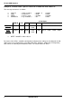
KS 800 CAN-Interface 3.2 Control Record (KS800 receive PDO): The structure of the Control Record is: Index Subindex Field Data Type 43 0 number of supported entries in the record unsigned8 1 channel number unsigned8 2 Wvol (set point) FixedPoint1 3 Yman (manual controller output) FixedPoint1 4 control byte unsigned8 5 update byte unsigned8 I.
KS 800 CAN-Interface 3.3 PDO transfer behaviour 3.3.1 Asynchronous send PDO When a PDO is configured as an asynchronous PDO, a PDO is sent with status-informationresp. Ypid- changes of a channel. The message order is: checking whether sending is necessary starts with the first channel. If a change-of-state is detected (flag fSendEvent set), a PDO is generated, sent and the flag is reset. After successful sending, the next channel is handled.
KS 800 CAN-Interface 3.3.2 Synchronous send PDO The master sends SYNC pulses for actual process value refreshment. The number of Sync messages after which must react can be configured by the master. The default setting is "1". (see Transfer-Type, chapter 3 Process-Data-Objekts) During synchronous operation, a channel starting with the first one is sent after each Sync message (if transfer-type = 1 ). Subsequently, all further channels are sent successively.
KS 800 CAN-Interface 3.3.4 Synchronous receive PDO When receiving a synchronous PDO, the data remain in the Rx buffer at first (CAN-controller) without being transmitted to the controller. For this, the received flag for the relevant channel is set. This signals that new data for the controller are ready for receiving. The fReceived flag is reset by the controller. The interaction of Sync message and synchronous PDOs is shown in the following diagram.
KS 800 CAN-Interface 4 OP mode / pre-OP mode After starting the CAN network, controller KS800 is in the pre-OP mode. I.e. it can be addressed only via SDOs. When setting KS800 to the OP mode, communication via the enabled PDOs is also possible. The asynchronous PDOs are enabled after start-up. If necessary, the synchronous PDOs must be enabled via SDO messages.
KS 800 CAN-Interface 5 SYNC As described above, synchronous PDO data must be read from or written to KS 800 by means of SYNC pulses. The relevant KS800 controllers must be in OP mode and the SYNC-PDOs must be enabled via SDO. For this, object "0x1800" must be set to value "0x280+nodes". A SYNC message is a "broadcast" (message to all units in the network) which is activated by the master as follows: 0 data bytes COB-ID LEN 0x80 2 Reply from KS800: e.g.
KS 800 CAN-Interface 6 Nodeguarding / Lifeguarding "Nodeguarding" can be used by a master for testing cyclically, if the relevant slave (KS800) is still in the network. The "guard time * life time" can be used to determine at which intervals the master must activate the nodeguard message (timeout for the master). With a "guard time * life time" = "0", no timeout for the master is determined, i.e. the master need not use a fixed time interval.
KS 800 CAN-Interface 7 LMT services (CMS standard and extensions) The LMT services according to CiA/DS205 version 1.1 are available. Restrictions, or special extensions are given in the following service descriptions. The relevant COB IDs are 2021 (master ⇒ slave), or 2020 (slave ⇒ master), whereby KS800 is slave. 7.1 Switch Mode Services 7.1.
KS 800 CAN-Interface 7.2 Configuration Services Configure NMT Address comprises services Configure Module ID and Configure Module Name. Service Configure Module Name is not supported. A relevant request provides error code: 255 and specific_error_code: 01 (service not supported). 7.2.
KS 800 CAN-Interface Service Activate Bit Timing is not supported (unconfirmed service !), activation is via a reset (see address/BR-switch for the 3 reset possibilities). Service Store Configuration is not supported. A relevant request provides error_code: 01 (service not supported). 7.3 Inquire LMT Address Inquire LMT address comprises the following 3 services: 7.3.
KS 800 CAN-Interface 7.3.3 Inquire Serial Number M⇒S 0 cs = 38 1 r 2 r 3 r 4 r 5 r 6 r 7 r 0 cs = 38 1 s1 2 s2 3 s3 4 s4 5 s5 6 s6 7 s7 S⇒M cs s1..s7 r LMT command specifier serial number of the module (if s1 is a valid BCD-pair). If s1 is 255, s2 contains error_code and s3 optional error reason. (provides the instrument code number) reserved 7.3.4 Serial Number Format (14 BCD-digit ⇒ 7 byte) 0 0 1 0 m1..m4 c1..c8 7.
KS 800 CAN-Interface 7.4.2 LMT Identify Slave S⇒M 0 cs = 09 cs r Notes: 7.5 1 r 2 r 3 r 4 r 5 r 6 r 7 r LMT command specifier reserved With several instruments connected to the bus, there may be problems, especially frame loss! (due to the number of simultaneously replying units with identical frames) Manufacturer-specific LMT services Service Activate Bit Timing (cs = 131) is not supported (see also Std. service with the same name). 7.
KS 800 CAN-Interface 7.6.1 Configure Module-ID M⇒S 0 cs = 129 1 MId 2 CAN 3 r 4 r 5 r 6 r 7 r 0 cs = 129 1 error code 2 spec error 3 r 4 r 5 r 6 r 7 r 3 CAN 4 r 5 r 6 r 7 r 3 r 4 r 5 r 6 r 7 r S⇒M cs CAN Mid error_code LMT command specifier number of CAN-controller (must be 0) new module_id to be configured 0: successful 1..
KS 800 CAN-Interface 7.6.
KS 800 CAN-Interface 8 Object directory The manufacturer-specific, list-oriented entries in the object directory are explained below. 8.1 Survey of object directory - manufacturer-specific section Note: The overall object directory is designed dually (from index 2001; from index 3001) to permit equal objectswith different data types. Index table structure: The index is a 4-digit number in hexadecimal notation with the following structure.
KS 800 CAN-Interface Column "as from firmware": Index (hex) Object (symbolic name) C = This datum exists already from operating version 1, however, it was subject to change (extension) in the course of development. N = This datum was added as from the specified operating version. Name Type Attribute as from firmware FB unit Process data fct.no.0 2001 VAR Status 1Unit-State1 Unsigned8 ro 1.0 2002 VAR Basic hardware options HWbas Unsigned16 ro 1.
KS 800 CAN-Interface 2027 VAR Forced dig. output OUT1...OUT8 Unsigned8 rw* 2.1 2028 VAR Forced dig. output OUT9...OUT16 Unsigned8 rw* 2.1 2029 VAR Forced dig. output OUT17...OUT19 Unsigned8 rw* see name FB input Process data fct. no. 0 2100 ARRAY Signal input fail Input_X_Failed Unsigned8 ro 1.0 2101 ARRAY Main variable x1 FixedPoint1 ro 1.0 2102 ARRAY Raw measurement value before meas.val.corr. INP1 FixedPoint1 ro 1.0 Parameter and configuration data fct. no.
KS 800 CAN-Interface 2206 ARRAY Controller self-tuning start OStart Unsigned8 rw 1.0 2207 ARRAY Switch-over Wext/Wint We/i Unsigned8 rw 1.0 2208 ARRAY Switch-over W/W2 w/W2 Unsigned8 rw 1.0 2209 ARRAY Controller on/off Coff Unsigned8 rw 1.0 Parameter and configuration data fct. no. 0 220A ARRAY Main configuration 1, control C100 Unsigned16 rw* 1.0 220B ARRAY Main configuration 2, control C101 Unsigned16 rw* 1.0 220C ARRAY Configuration tuning C700 Unsigned16 rw* 1.
KS 800 CAN-Interface Process data fct. no. 4 2240 ARRAY Difference correcting variable dYman FixedPoint1 rw 1.0 2241 ARRAY Absolute correcting variable Yman FixedPoint1 rw 1.0 2242 ARRAY Increm. adjustment of correcting variable Yinc Unsigned8 rw 1.0 2243 ARRAY Decrem. adjustment of correcting variable Ydec Unsigned8 rw 1.0 2244 ARRAY Speed for increm. and decrem. adjustment of correcting variable Ygrw_is Unsigned8 rw 1.0 Parameter and configuration data fct. no.
KS 800 CAN-Interface 2263 ARRAY Min. cycle time 1 T1_1 FixedPoint1 rw 1.0 2264 ARRAY Proportional band 2 Xp2_1 FixedPoint1 rw 1.0 2265 ARRAY Integral time 2 Tn2_1 FixedPoint1 rw 1.0 2266 ARRAY Derivative time 2 Tv2_1 FixedPoint1 rw 1.0 2267 ARRAY Min. cycle time 2 T2_1 FixedPoint1 rw 1.0 Parameter and configuration data fct. no. 7 2270 ARRAY Proportional band 1 Xp1_2 FixedPoint1 rw 1.0 2271 ARRAY Integral time 1 Tn1_2 FixedPoint1 rw 1.
KS 800 CAN-Interface Column "as from firmware": Index (hex) Object (symbolic name) C = This datum exists already from operating version 1, however, it was subject to change (extension) in the course of development. N = This datum was added as from the specified operating version. Name Type Attribute as from firmware FB unit Process data fct.no.0 3001 VAR Status 1Unit-State1 Unsigned8 ro 1.0 3002 VAR Basic hardware options HWbas Unsigned16 ro 1.
KS 800 CAN-Interface 3028 VAR Forced dig. output OUT9...OUT16 Unsigned8 rw* 2.1 3029 VAR Forced dig. output OUT17...OUT19 Unsigned8 rw* see name FB input Process data fct. no. 0 3100 ARRAY Signal input fail Input_X_Failed Unsigned8 ro 1.0 3101 ARRAY Main variable x1 FixedPoint1 ro 1.0 3102 ARRAY Raw measurement value before meas.val.corr. INP1 FixedPoint1 ro 1.0 Parameter and configuration data fct. no.
KS 800 CAN-Interface 3207 ARRAY Switch-over Wext/Wint We/i Unsigned8 rw 1.0 3208 ARRAY Switch-over W/W2 w/W2 Unsigned8 rw 1.0 3209 ARRAY Controller on/off Coff Unsigned8 rw 1.0 Unsigned16 rw* 1.0 Unsigned16 rw * 1.0 * 1.0 Parameter and configuration data fct. no. 0 320A 320B ARRAY ARRAY Main configuration 1, control C100 Main configuration 2, control C101 320C ARRAY Configuration tuning C700 Unsigned16 rw 320D ARRAY Signal allocation anal. C180 Unsigned16 rw* 1.
KS 800 CAN-Interface Process data fct. no. 4 3240 ARRAY Difference correcting variable dYman FixedPoint1 rw 1.0 3241 ARRAY Absolute correcting variable Yman FixedPoint1 rw 1.0 3242 ARRAY Increm. adjustment of correcting variable Yinc Unsigned8 rw 1.0 3243 ARRAY Decrem. adjustment of correcting variable Ydec Unsigned8 rw 1.0 3244 ARRAY Speed for increm. and decrem. adjustment of correcting variable Ygrw_is Unsigned8 rw 1.0 Parameter and configuration data fct. no.
KS 800 CAN-Interface 3263 ARRAY Min. cycle time 1 T1_1 FixedPoint1 rw 1.0 3264 ARRAY Proportional band 2 Xp2_1 FixedPoint1 rw 1.0 3265 ARRAY Integral time 2 Tn2_1 FixedPoint1 rw 1.0 3266 ARRAY Derivative time 2 Tv2_1 FixedPoint1 rw 1.0 3267 ARRAY Min. cycle time 2 T2_1 FixedPoint1 rw 1.0 Parameter and configuration data fct. no. 7 3270 ARRAY Proportional band 1 Xp1_2 FixedPoint1 rw 1.0 3271 ARRAY Integral time 1 Tn1_2 FixedPoint1 rw 1.
KS 800 CAN-Interface 9 Configuration and parameter setting via the CAN bus The following versions are of importance only in case of KS 800 configuration and parameter setting via the CAN bus. Normally, the engineering tool is used for this purpose, whereby mutual configuration data checking and correct order of data during download are already taken into account. The order in which the data must be sent to KS 800 for correct configuration and parameter setting is specified in the list given below.
KS 800 CAN-Interface 9.2 Data plausibility check during transmission Caution! The configuration data are not checked by the instrument. (This check is done only in the engineering tool.) The parameter data are checked for their limits. 9.3 Table of allocation of firmware version, operating version, series number and engineering tool. Date Seriesnumber Firmware version Operat. version 3.8.97 8330 1.0 1 1.0 10.9.97 8334 1.1 1 1.1 28.10.97 8335 1.2 1 1.1 16.12.97 8337 1.3 1 1.1 8.4.
KS 800 CAN-Interface 9.4 Order of data for configuration and parameter setting Column "Function" gives the configuration data the signification of which is described in detail in description manual 9499 040 49218. The digits behind the _(underscore) indicate the digits used in the configuration word. 16 15 14 13 12 Digit 4 11 10 9 8 Digit 3 7 6 5 4 3 Digit 2 2 1 Digit 1 Column "Introduction" gives the operating version in which a configuration datum was introduced.
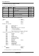
KS 800 CAN-Interface Instrument parameters 2010 par_wk_enable ab BV ≥ 2 Channel parameters 2214 2215 2216 2217 2218 2219 2230 (2230 2231 (2231 2232 2233 2234 2235 2236 2237 2245 2246 2247 2248 2249 225B 225C 225E 225F 225D 2260 2261 par_w0 BV 1 par_w100 BV 1 par_w2 BV 1 par_grwp BV 1 par_grwm BV 1 par_grw2 BV 1 par_xsh BV 1 par_xsh_wk) BV 1 par_tpuls BV 1 par_tpuls_wk) BV 1 par_tm BV 1 par_xsd1 BV 1 par_lw BV 1 par_xsd2 BV 1 par_xsh1 BV 1 par_xsh2 BV 1 par_ymin BV 1 par_ymax BV 1 par_y0 BV 1 par_yh BV 1
KS 800 CAN-Interface 10 Application example 10.1 KS800 standard settings KS800 is factory-set to the default parameters given in the controller description. As a heating/ cooling controller is required for the example and a H controller is adjusted as standard, alteration via SDOs is required. 10.2 Adjusting a heating/cooling controller Adjusting a standard controller (only heating) as a heating/cooling controller and reading the process value cyclically (via SDOs) are done as described below.
KS 800 CAN-Interface 10.3 Adjusting a H/C controller and activating the self-tuning Adjusting a standard controller (H) as a H/C controller via SDOs, starting the self-tuning and reading the actual process values (via SDOs) are done as described below. As only channel 1 is required, the subindex for the channel number must be set to "1".
KS 800 CAN-Interface else { /* possible error message: no set-point reserve → increase Weff */ read error message heating → Index 0x3256 (MSG1) Reference: controller, individual code 35 - read error message cooling → Index 0x325A (MSG1) Reference: controller, individual code 39 { 42 9499 040 49511
KS 800 CAN-Interface 11 CAN Physical Layer Related to the CAN Physical Layer, there are a number of standards. The most important standard for general applications is the "CAN High-Speed Standard ISO 11898-2". The recommendations given below are based primarily on this standard and are valid independent of the used CAN protocol (CANopen / DeviceNet). 11.
KS 800 CAN-Interface 11.2 Bit rates and bus lengths: The maximum useful bus length in a CAN network is determined by a variety of physical effects, in particular: The delay time of the connected bus nodes (with/without opto-couplers) and the delay time of the bus cable (propagation delays), various scanning times within a CAN bit cell due to the oscillator tolerances of bus nodes, signal amplitude attenuation due to the DC resistance of the bus cable and the input resistances of bus nodes.
KS 800 CAN-Interface 11.4 Cable parameters ISO 11898-2 defines some DC or AC parameters for the cables which can be used in CAN bus networks (typically, pairwisely twisted cables with defined electrical properties are used). The important AC parameters are 120 Ohm cable impedance and a nominal _propagation delay_ of 5 ns/m ! Recommendations for the bus cables and terminating resistors are given in the following table: Bus-length Bus-cabel (Z: 120 Ohm, tp: 5ns/m Spec.
Subject to alteration without notice. Printed in Germany 9499 040 49511 (10/2004) © PMA Prozeß- und Maschinen-Automation GmbH P.O.B.