
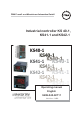
Instruction Manual
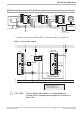

Connection of input INP2 3
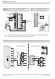
Heating current input (0...50mA AC) or in
-
put for ext. set-point (0/4...20mA)
Connection of input di1 4
Digital input, configurable as switch or
push-button
Connection of outputs OUT1/2 5
Relay outputs 250V/2A normally open with
common contact connection
Connection of output OUT3 6
a relay (250V/2A), potential-free
changeover contact
universal output
b current (0/4...20mA)
c voltage (0/2...10V)
d transmitter supply
e logic (0..20mA / 0..12V)
Connection of inputs di2/3 7 (option)
Digital inputs (24VDC external), galvani-
cally isolated, configurable as switch or
push-button
Connection of output U
T
8 (option)
Supply voltage connection for external ener
-
gization
Connection of bus interface 9 (option)
RS422/485 interface with Modbus RTU
protocol
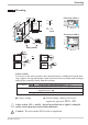
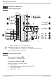
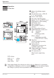
Electrical connections
Operating KS4x-1 7 Terminal connection
1
2
3
4
7
5
8
6
9
10
11
12
13
14
15
L
N
+
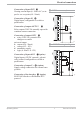
5 OUT1/2 heating/cooling
1
2
3
4
7
5
8
6
9
10
11
12
13
14
15
L
N
Logic
+
_
SSR
3 INP2 current tansformer