
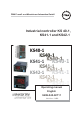
Instruction Manual

2 Electrical connections
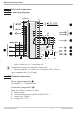
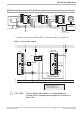
2.1 Connecting diagram
* Safety switch mA i V in position left
g
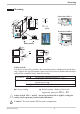
Dependent of order, the controller is fitted with :
w
flat-pin terminals 1 x 6,3mm or 2 x 2,8mm to DIN 46 244 or
screw terminals for 0,5 to 2,5mm²
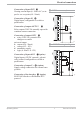
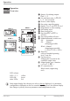
2.2 Terminal connection
Power supply connection 1
See chapter 11 "Technical data"
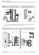
Connection of input INP1 2
Input for variable x1 (process value)
a thermocouple
b resistance thermometer (Pt100/ Pt1000/ KTY/ ...)
c current (0/4...20mA)
d voltage (0/2...10V)
Electrical connections
Connecting diagram 6 Operating KS4x-1
U
Logic
di2
di3
U
T
Option
RXD-B
GND
RXD-A
TXD-B
TXD-A
RS485 RS422
Modbus RTU
RGND
DATA B
DATA A
L
N
90...250V
24V AC/DC
mA
mA
0..10 V*
HC
di1
INP1
INP2
OUT3
OUT2
OUT1
1
2
3
4
7
5
8
6
9
10
11
12
13
14
15
1
3
4
5
6
7
8
9
10
11
12
13
14
15
17
(2)
(16)
a
b
c
d
a
b
c
d
e