
Instruction Manual


11 Technical data
INPUTS
PROCESS VALUE INPUT INP1
Resolution: > 14 bits
Decimal point: 0 to 3 digits behind the decimal point
Dig. input filter: adjustable 0,000...9999 s
Scanning cycle: 100 ms
Measured value
correction:
2-point or offset correction
Thermocouples
r Table 1 (page 53 )
Input resistance: ³1MW
Effect of source resistance: 1 mV/W
Cold-junction compensation
Maximal additional error: ± 0,5 K
Sensor break monitoring
Sensor current: £ 1
m
A
Configurable output action
Resistance thermometer
r Table 2 (page 53 )
Connection: 2 or 3-wire
Lead resistance: max. 30 Ohm
Input circuit monitor: break and short circuit
Special measuring range
BlueControl (engineering tool) can be used to
match the input to sensor KTY 11-6
(characteristic is stored in the controller).
Physical measuring range: 0...4500 Ohm
Linearization segments 16
Current and voltage signals
r Table 3 (page 53 )
Span start, end of
span:
anywhere within measuring
range
Scaling: selectable -1999...9999
Linearization: 16 segments, adaptable with
BlueControl
Decimal point: adjustable
Input circuit monitor: 12,5% below spanstart(2mA, 1V)
SUPPLEMENTARY INPUT INP2
Resolution: > 14 bits
Scanning cycle: 100 ms
Accuracy: < 0,5 %
Heating current measurement
via current transformer (® Accessory equipment)
Measuring range: 0...50mA AC
Scaling: adjustable -1999...0,000...9999 A
Current measuring range
Technical data as for INP1
CONTROL INPUT DI1
Configurable as switch or push-button!
Connection of a potential-free contact suitable
for switching “dry” circuits.
Switched voltage: 2,5 V
Current: 50 mA
CONTROL INPUTS DI2, DI3 (OPTION)
Configurable as switch or push-button!
Optocoupler input for active triggering
Nominal voltage 24 V DC external
Current sink (IEC 1131 type 1)
Logic “0” -3...5 V
Logic “1” 15...30 V
Current requirement approx.. 5 mA
TRANSMITTER SUPPLY UT (OPTION)
Power: 22 mA / ³18 V
If the universal output OUT3 is used there may
be no external galvanic connection between
measuring and output circuits!
GALVANIC ISOLATION
Safety isolation
Function isolation
OUTPUTS
RELAY OUTPUTS OUT1, OUT2
Contact type: 2 NO contacts with common
connection
Max. contact rating: 500 VA, 250 V, 2A at 48...62Hz,
resistive load
Min. contact rating: 6V, 1 mA DC
Technical data
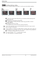
Operating KS4x-1 51
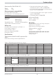
Power supply
connections
Process value input INP1
Supplementary input INP2
Digital input di1
Relay outputs OUT 1,2 RS422/485 interface
Relay output OUT3 Digital inputs di2, 3
Universal output OUT3
Transmitter supply U
T