
Instruction Manual
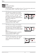
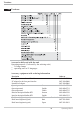

Mode 6
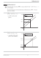
After set-point switch-over (SPr SP.2),
control is to SP.2. The timer (t.SP) starts
when the process value enters the adjusted
band around the set-point (x = SP.2 _ b.ti).
After time elapse the controller returns to SP.
End and the set-point are displayed alternate
-
ly in the lower display line.
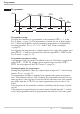
8.1.2 Tolerance band
Timer modes 1,2 and 6 are provided with a freely adjustable tolerance band. The
tolerance band around the set-point can be adjusted via parameter b.ti in the
Conf menu (x = SP.2 _ b.ti )
(r page 21).
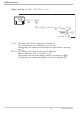
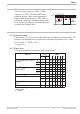
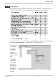
8.1.3 Timer start
Various procedures for starting the timer are possible:
Timer
Operating KS4x-1 47 Setting up the timer
Start via LOGI Mode
Y2
=
SP.2
=
123456
Y / Y2 switch-over via digital
input
1
di1 2 x ddddd-
di2 3 x ddddd-
di3 4 x ddddd-
SP / SP.2 switch-over via
digital input
1
di1 x 2 - - - - - d
di2 x 3 - - - - - d
di3 x 4 - - - - - d
Pressing key Ò 6xddddd-
Power On 0 x ddddd-
x 0-----d
Changing t.ti (extended operating
level)
xxdddddd
Serial interface (if provided) x x dddddd
1
when using a digital input, adjust parameter di.Fn = 2 ( ConF/ LOGI)
( key function)
x no effect
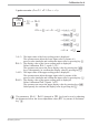
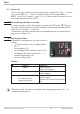
Start
t.SP
SP
SP
blinks
u
u
SP.2 b.ti_
End
run
run
SP.2