PMA Prozeß- und Maschinen-Automation GmbH Industrial controller KS 40-1, KS41-1 and KS42-1 KS40-1 KS41-1 KS40-1 KS42-1 KS41-1 KS42-1 Operating manual English 9499-040-62711 Valid from: 8499
û BlueControl® More efficiency in engineering, more overview in operating: The projecting environment for the BluePort® controllers on ! s ON ate I pd de T N U e. E and nlin D T ATrsion ma-o A-C e .p PM V ni ww r on i M w o Description of symbols in the text: on the device: g General information a Follow the operating instructions a General warning l Attention: ESD-sensitive devices © PMA Prozeß- und Maschinen-Automation GmbH • Printed in Germany All rights reserved.
Contents 1 2 2.1 2.2 3 3.1 3.2 3.3 3.4 3.5 3.5.1 3.5.2 3.5.3 3.5.4 3.5.5 3.5.6 3.6 3.7 3.8 4 4.1 4.2 4.3 4.4 4.4.1 4.4.2 4.4.3 4.4.4 4.4.5 4.4.6 4.4.7 Mounting . . . . . . . . . . . . . . . . . . . . . . . . . . . . . . 5 Electrical connections . . . . . . . . . . . . . . . . . . . . . . . 6 Connecting diagram. . . . . . . . . . . . . . . . . . . . . . . . . 6 Terminal connection . . . . . . . . . . . . . . . . . . . . . . . . 6 Operation . . . . . . . . . . . . . . . . . . . . . . . . . . . . .
5 5.1 5.2 5.3 5.4 5.5 5.5.1 5.5.2 6 7 8 8.1 Parameter setting level . Parameter survey . . . . . . . . . . . . . . . . . . . . . . . . . . . . . . . . Parameters . . . . . . . . Input scaling . . . . . . . . . . . . . . . . . . . . . . . . . . . . . . . . . . . . . . . . . . . . . . . . . . . . . . . . . . . . . . . . . . . . . . . . . . . . . . . . . . . . . . . . . . . . . . . . . . . . . . . . . . . . . . . . . . . . . . . . . . . . . . . . . . . . . 37 37 37 37 38 40 Input Inp.
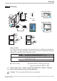
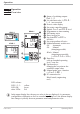
Mounting 1 Mounting min.48 (1.89") 96 (3.78") SP.X 126 125 45 run Ada 60°C min. 0°C 48 (1.89") ( +0,8 8 max. 92 11 5 6 4. (0 1. .0 .1 4. 0 .0 .4 ") 10 ( ") (3.62" +0.03) ") 4 0. Front view KS41-1 max. 95% rel. 126. 125 +0,6 Front view KS42-1 96 (3.78") SP.x 10V i mA/Pt Loc Err 96 (3.78") KS 40-1 universal 48 (1.89") run Ada KS 41-1 universal % (1.77" +0.02) Err SP.x mA/Pt Loc Loc 10V 10V mA/Pt Err 125 KS 42-1 universal Loc 10V mA/Pt Safety switch 126.
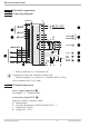
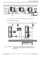
Electrical connections 2 Electrical connections 2.1 Connecting diagram Option 1 di2 2 3 di3 UT 5 RGND DATA B DATA A RS485 * g 5 7 6 a Logic 8 11 9 12 GND 13 RXD-A 14 TXD-B 15 (16) 17 RS422 OUT1 OUT2 d e c b 7 10 RXD-B TXD-A 4 6 9 Modbus RTU 3 4 8 90...250V 24V AC/DC L N 1 (2) OUT3 U 10 HC mA 11 12 INP2 di1 13 mA 14 0..
Electrical connections Connection of input INP2 3 Heating current input (0...50mA AC) or input for ext. set-point (0/4...20mA) 3 INP2 current tansformer L 1 Connection of input di1 4 Digital input, configurable as switch or push-button 2 3 4 5 6 Connection of outputs OUT1/2 5 Relay outputs 250V/2A normally open with common contact connection Logic SSR _ 7 8 + 9 10 11 Connection of output OUT3 6 a relay (250V/2A), potential-free changeover contact universal output b current (0/4...
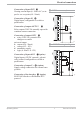
Electrical connections 7 8 di2/3, UT 2-wire transmitter supply 6 OUT3 transmitter supply Option 5mA +24VDC - 1 1 (2) 2 3 5mA 0V + 17,5V 22mA - + 3 4 5 4 6 5 7 6 8 9 7 10 8 11 9 OUT3 + 12 + 10 13 1 11 14 3 12 15 K 13 (16) 2 - 13V 22mA 14 17 15 - + 2 - 3 K J 1 x U and the universal output OUT3 is used there may be no external galvanic a Ifconnection between measuring and output circuits! T 6 OUT3 as logic output with solid-state relay (series and paralle
Electrical connections 9 RS485 interface (with RS232-RS485 interface converter) * 12 RGND RT = 120...200 Ohm 11 14 DATA B RT 12 DATA B 13 (16) DATA A 14 17 13 14 12 15 DATA A RGND 10 13 15 15 (16) 17 12 10 RGND 11 12 11 14 DATA B 13 14 10 13 13 (16) DATA A 15 PC 12 15 14 17 15 R=100 Ohm converter RS485-RS232 max. 1000m ”Twisted Pair” RGND connection optional J * RT RT = 120...200 Ohm Interface description Modbus RTU in seperate manual: see page 50.
Operation 3 Operation 3.1 Front view SP.x 126. 125 1 run Err 3 OK 2 Err 9 0 ! KS42-1 Ada 2 run Ada KS 41-1 universal SP.x 1 KS40-1 KS41-1 SP.x 126. 125 126. 125 run Ada Err 3 5 6 7 8 4 $ " % § KS 42-1 universal KS 40-1 universal 1 Status of switching outputs OuT.1...
Operation 3.2 Behaviour after power-on After supply voltage switch-on, the unit starts with the operating level. The unit is in the condition which was active before power-off. If KS4x-1 was in manual mode before power-off, the controller starts with correcting value Y2 after switching on again. 3.3 Operating level The content of the extended operating level is determined by means of BlueControl (engineering tool).
Operation 3.4 Maintenance manager / Error list With one or several errors, the extended operating level always starts with the error list. Signalling an actual entry in the error list (alarm, error) is done by the Err LED in the display. To reach the error list press Ù twice. Err LED status blinks (Status 2) lit (Status 1) off (Status 0) SP.x 126 125 run Ada Err Proceed as follows - Determine the error type in the error list via the error number - -Change to status 1 after error removal.
Operation Name Description LooP Control loop alarm (LOOP) AdA.H Self-tuning heating alarm (ADAH) AdA.C Self-tuning heating alarm cooling (ADAC) LiM.1 stored limit alarm 1 Lim.2 stored limit alarm 2 Lim.3 stored limit alarm 3 Inf.1 time limit value message Inf.
Operation 3.5 Self-tuning For determination of optimum process parameters, self-tuning is possible. After starting by the operator, the controller makes an adaptation attempt, whereby the process characteristics are used to calculate the parameters for fast line-out to the set-point without overshoot. The following parameters are optimized when self-tuning: Parameter set 1: Pb1 - Proportional band 1 (heating) in engineering units [e.g.
Operation Start condition: w Rest condition For process evaluation, a stable condition is required. Therefore, the controller waits until the process has reached a stable condition after self-tuning start. The rest condition is considered being reached, when the process value oscillation is smaller than ± 0,5% of (rnG.H - rnG.L). Set-point reserve After having come to rest with 0% correcting variable or with Y.
Operation 3.5.5 Acknowledgement procedures in case of unsuccessful self-tuning 1. Press keys Ù and È simultaneously: The controller continues controlling using the old parameters in automatic mode. The Err LED continues blinking, until the self-tuning error was acknowledged in the error list. 2. Press key Ò (if configured): The controller goes to manual mode. The Err LED continues blinking, until the self-tuning error was acknowleged in the error list. 3.
Operation Start: at set-point Heating power Y is switched off (1). If the change of process value X was constant during one minute and the control deviation is > 10% of SP.Hi SP.LO (2), the power is switched on (3). At the reversal point, the self-tuning attempt is finished, and control to set-point W is using the new parameters. X W 2 100% Y 0% start r t 1 3 t reversal point blinks X Three-point controller W The parameters for heating and cooling are determined in two attempts.
Operation The control parameters can be determined from the values calculated for delay time Tu , maximum rate of increase vmax, control range Xh and characteristic K according to the formulas given below. Increase Xp, if line-out to the set-point oscillates.
Operation Ü Operaing principle absolut alarm L.1 = OFF InL.1 * Operating principle relative alarm L.1 = OFF InH.1 SP InL.1 InH.1 H.1 H.1 HYS.1 HYS.1 LED LED 1 1 2 H.1 = OFF 2 H.1 = OFF InL.1 InH.1 SP InL.1 InH.1 L.1 L.1 HYS.1 HYS.1 LED LED 2 2 1 InL.1 InH.1 1 SP InL.1 InH.1 H.1 L.1 L.1 HYS.1 H.1 HYS.1 HYS.1 LED LED 1 2 HYS.1 2 LED LED 1 2 2 1: normally closed ( ConF/ Out.x / O.Act=1 ) 2: normally open ( ConF/ Out.x / O.
Operation g If measured value monitoring + alarm status storage is chosen ( ConF / Lim / Fnc.x = 2), the alarm relay remains switched on until the alarm is resetted in the error list ( Lim 1..3 = 1). 3.8 Operating structure After supply voltage switch-on, the controller starts with the operating levels. The controller status is as before power off. 126 Ù 125 3 sec.
Configuration level 4 Configuration level 4.1 Configuration survey C.Fnc Corr mAn C.Act FAIL rnG.L rnG.H Fnc.2 Y.2 Src.2 Lim.1 Fnc.3 Lim.2 Src.3 Lim.3 HC.AL LP.AL LP.AL HC.AL HC.SC time P.End FAi.1 FAi.2 See output 1 È SP.Fn StYP I.Fnc Fnc.1 O.Act Ì b.ti S.Lin StYP Src.1 Y.1 O.tYP O.Act Y.1 Y.2 Lim.1 Lim.2 Lim.3 LP.AL HC.AL HC.SC time P.End FAi.1 FAi.2 OuT.0 Out.1 O.Src End Othr Display, operation, interface LOGI Digital inputs OUt.1 Output 1 OUt.2 Output 2 OUt.
Configuration level 4.2 Configuration Cntr Name SP.Fn b.ti C.Fnc mAn C.Act FAIL rnG.L rnG.H Adt0 Value range Description Default 0 Basic configuration of setpoint processing 0 set-point controller can be switched over to external set-point (® LOGI/SP.
Configuration level InP.1 Name Value range Description Default 1 Sensor type selection 0 thermocouple type L (-100...900°C) , Fe-CuNi DIN 1 thermocouple type J (-100...1200°C) , Fe-CuNi 2 thermocouple type K (-100...1350°C), NiCr-Ni thermocouple type N (-100...1300°C), Nicrosil-Nisil 3 thermocouple type S (0...1760°C), PtRh-Pt10% 4 thermocouple type R (0...1760°C), PtRh-Pt13% 5 20 Pt100 (-200.0 ... 100,0 °C) 21 Pt100 (-200.0 ... 850,0 °C) 22 Pt1000 (-200.0 ... 200.0 °C) 23 special 0...
Configuration level Lim Name Fnc.1 Fnc.2 Fnc.3 Src.1 Src.2 Src.3 HC.AL LP.AL Hour Swit Value range Description Default 1 Function of limit 1/2/3 0 switched off 1 measured value monitoring 2 Measured value monitoring + alarm status storage. A stored limit value can be reset via error list, Ò-key or a digital input ( ® LOGI/ Err.r).
Configuration level Name HC.SC timE P.End FAi.1 FAi.2 fOut Value range Description Solid state relay (SSR) short circuit signal 0 not active 1 active Timer end signal 0 not active 1 active Programmer end signal 0 not active 1 active INP1/ INP2 error signal 0 not active 1 active Forcing OUT1 (only visible with BlueControl!) 0 No forcing 1 Forcing via serial interface Default 0 0 0 0 0 Out.2 Configuration parameters Out.2 as Out.1 except for: Default Y.1 = 0 Y.2 = 1 Out.3 Name O.tYP O.Act Y.
Configuration level Name HC.SC timE P.End FAi.1 FAi.2 Out.0 Out.1 O.Src fOut g Value range Description Default 0 Solid state relay (SSR) short circuit signal (only visible when O.TYP=0) 0 not active 1 active 0 Timer end signal (only visible when O.TYP=0) 0 not active 1 active 0 Programmer end signal (only visible when O.TYP=0) 0 not active 1 active 1 INP1/ INP2 error (only visible when O.TYP=0) 0 not active 1 active -1999...
Configuration level Name SP.E Y2 mAn C.oFF m.Loc Err.r P.run di.Fn fDI1 Operating KS4x-1 Value range Description Switching to external setpoint SP.
Configuration level Name fDI2 fDI3 Value range Description Forcing di2 (only visible with BlueControl!) 0 No forcing 1 Forcing via serial interface Forcing di3 (only visible with BlueControl!) 0 No forcing 1 Forcing via serial interface Default Value range Description Baudrate of the interface (only visible with OPTION) 0 2400 Baud 1 4800 Baud 2 9600 Baud 3 19200 Baud 1...
Configuration level Name Value range Description Block parameter level (only visible with BlueControl!) 0 Released 1 Blocked Block configuration level (only visible with BlueControl!) 0 Released 1 Block Block calibration level (only visible with BlueControl!) 0 Released 1 Blocked IPar ICnf ICal + BlueControl - the engineering tool for the BluePort Default 1 1 1 â controller series 3 engineering tools with different functionality facilitating KS4x-1 configuration and parameter setting are available
Configuration level 4.4 Configuration examples 4.4.1 On-Off controller / Signaller (inverse) InL.1 SP.LO SP SP.Hi InH.1 InP.1Ê 100% SH Out.1Â 0% ConF / Cntr: SP.Fn C.Fnc C.Act ConF / Out.1: O.Act Y.1 SH PArA / Cntr: PArA / SEtP: g SP.LO SP.Hi = 0 = 0 = 0 set-point controller signaller with one output inverse action (e.g. heating applications) = 0 action Out.1 direct = 1 control output Y1 active = 0...9999 switching difference (symmetrical to the trigger point) = -1999...
Configuration level 4.4.2 2-point controller (inverse) InL.1 SP.LO InP.1Ê SP SP.Hi InH.1 PB1 100% Out.1Â 0% ConF / Cntr: SP.Fn C.Fnc C.Act ConF / Out.1: O.Act Y.1 Pb1 PArA / Cntr: PArA / SEtP: g ti1 td1 t1 SP.LO SP.Hi = 0 = 1 = 0 set-point controller 2-point controller (PID) inverse action (e.g. heating applications) = 0 action Out.1 direct = 1 control output Y1 active = 0,1...9999 proportional band 1 (heating) in units of phys. quantity (e.g. °C) = 1...
Configuration level 4.4.3 3-point controller (relay & relay) InL.1 SP.LO InP.1Ê SP PB1 100% SP.Hi InH.1 PB2 100% Out.1Â Out.2Â 0% 0% ConF / Cntr: SP.Fn C.Fnc C.Act ConF / Out.1: O.Act Y.1 Y.2 O.Act Y.1 Y.2 Pb1 ConF / Out.2: PArA / Cntr: Pb2 PArA / SEtP: Configuration examples ti1 ti2 td1 td2 t1 t2 SH SP.LO SP.Hi = 0 = 3 = 0 set-point controller 3-point controller (2xPID) action inverse (e.g. heating applications) = 0 action Out.
Configuration level 4.4.4 3-point stepping controller (relay & relay) InL.1 SP.LO InP.1Ê SP SP.Hi InH.1 PB1 100% 100% SH Out.1Â 0% SP.Fn C.Fnc C.Act = 0 = 4 = 0 ConF / Out.1: O.Act Y.1 Y.2 O.Act Y.1 Y.2 Pb1 = = = = = = = ti1 td1 t1 SH tP tt SP.LO SP.Hi = = = = = = = = PArA / Cntr: PArA / SEtP: g 0% ConF / Cntr: ConF / Out.2: Out.2Â set-point controller 3-point stepping controller inverse action (e.g. heating applications) 0 action Out.
Configuration level 4.4.5 Continuous controller (inverse) SP.LO InL.1 InP.1Ê SP SP.Hi InH.1 PB1 20 mA Out.3Â 0/4 mA ConF / Cntr: SP.Fn C.Fnc C.Act = 0 = 1 = 0 ConF / Out.3: O.tYP Out.0 Out.1 Pb1 = = = = 1/2 -1999...9999 -1999...9999 0,1...9999 ti1 td1 t1 SP.LO SP.Hi = = = = = 1...9999 1...9999 0,4...9999 -1999...9999 -1999...9999 PArA / Cntr: PArA / SEtP: set-point controller continuous controller (PID) inverse action (e.g. heating applications) Out.
Configuration level 4.4.6 D - Y - Off controller / 2-point controller with pre-contact InL.1 SP.LO SP InP.1Ê SP.Hi InH.1 PB1 100% Out.1Â 0% Out.2Â SH ConF / Cntr: SP.Fn C.Fnc C.Act d.SP = 0 = 2 = 0 set-point controller D -Y-Off controller inverse action (e.g. heating applications) ConF / Out.1: O.Act = 0 action Out.1 direct Y.1 = 1 control output Y1 active Y.2 = 0 control output Y2 not active ConF / Out.2: O.Act = 0 action Out.2 direct Y.1 = 0 control output Y1 not active Y.
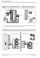
Configuration level 4.4.7 KS4x-1 with measured value output phys. quantity Out.1 mA / V phys. quantity Out.0 20mA 10V 0/4mA 0/2V L N 1 2 } 90...250VAC 24VUC 3 4 5 6 7 U OUT3 8 9 10 11 12 13 14 INP1 15 ConF / Out.3: Configuration examples O.tYP + 1 2 3 4 -1999...9999 Out.0 = = = = = Out.1 = -1999...9999 O.Src = 3 Out.3 0...20mA continuous Out.3 4...20mA continuous Out.3 0...10V continuous Out.3 2...10V continuous scaling Out.3 for 0/4mA or 0/2V scaling Out.
Parameter setting level 5 Parameter setting level 5.1 Parameter survey SP.Lo SP.Hi SP.2 r.SP t.SP End Inl.2 OuL.2 InH.2 OuH.2 Lim InL.1 OuL.1 InH.1 OuH.1 tF.1 Limit value functions Input 2 Input 1 Programmer Prog SP.01 Pt.01 SP.02 Pt.02 SP.03 Pt.03 SP.04 Pt.04 InP.2 Pb1 Pb2 ti1 ti2 td1 td2 t1 t2 SH d.SP tP tt Y2 Y.Lo Y.Hi Y0 Ym.H L.Ym InP.1 Ì SEtP Set-point and process value È Cntr Control and self-tuning PArA Parameter setting level L.1 H.1 HYS.1 L.2 H.2 HYS.2 dEl.2 L.3 H.3 HYS.3 HC.
Parameter setting level 5.2 Parameters Cntr Name Pb1 Pb2 ti1 ti2 td1 td2 t1 t2 SH d.SP tP tt Y2 Y.Lo Y.Hi Y.0 Ym.H L.Ym 1 Value range Description Default 1...9999 1 Proportional band 1/2 (heating) in phys. dimensions (e.g. °C) 100 1...9999 1 Proportional band 2 (cooling) in phys. dimensions (e.g. °C) 100 1...9999 180 Integral action time 1 (heating) [s] 1...9999 180 Integral action time 2 (cooling) [s] 1...9999 180 Derivative action time 1 (heating) [s] 1...
Parameter setting level Name Value range Description Default SP.04 -1999...9999 Segment end set-point 4 0...9999 Pt.04 Segment time 4 [min] 1 If SP.01 … SP.04 = OFF then following parameters are not shown 2 If segment end set-point = OFF then the segment time is not visible 200 1 10 2 InP.1 Name InL.1 OuL.1 InH.1 OuH.1 t.F1 Value range Description -1999...9999 Input value for the lower scaling point -1999...9999 Displayed value for the lower scaling point -1999...
Parameter setting level 5.3 Input scaling When using current or voltage signals as input variables for InP.1 or InP.2, scaling of input and display values at parameter setting level is required. Specification of the input value for lower and higher scaling point is in the relevant electrical unit (mA / V). phys. quantity OuH.x phys. quantity mA / V OuL.x InH.x mA/V InL.x 5.3.1 Input Inp.1 g Parameters InL.1 , OuL.1, InH.1 and OuH.1 are only visible if ConF / InP.1 / Corr = 3 is chosen. S.tYP 30 (0.
Calibration level 6 Calibration level g Measured value correction ( CAL) is only visible if ConF / InP.1 / Corr = 1 or 2 is chosen. The measured value can be matched in the calibration menu ( CAL). Two methods are available: Offset correction ( ConF/ InP.1 / Corr =1 ): display standard setting offset correction w possible on-line at the process OuL.1new OuL.1old InL.1 X 2-point correction ( ConF/ InP.
Calibration level Offset correction ( ConF/ InP.1 / Corr =1 ): r SP.X 126 125 run Ada Err r Ù r PArA 3 sec. Ì : CAL r Ù r InP.1 r Ù r InL.1 r Ù r OuL.1 È r Ù Ì r End r Ù InL.1: The input value of the scaling point is displayed. The operator must wait, until the process is at rest. Subsequently, the operator acknowledges the input value by pressing key Ù. OuL.1: The display value of the scaling point is displayed. Before calibration, OuL.1 is equal to InL.1.
Calibration level 2-point correction ( ConF/ InP.1 / Corr =1 ): r SP.X 126 r Ù r 125 run Ada Err 3 sec. PArA Ì : CAL r Ù r InP.1 r Ù r InL.1 r Ù r OuL.1 È r Ù Ì r InH.1 r Ù r OuH.1 È r Ù Ì r End r Ù InL.1: The input value of the lower scaling point is displayed. The operator must adjust the lower input value by means of a process value simulator and confirm the input value by pressing key Ù. OuL.1: The display value of the lower scaling point is displayed. Before calibration, OuL.1 equals InL.1.
Programmer 7 Programmer W,X SP.01 SP.02 SP.03 SP.04 W,X W Pt.01 Pt.02 Pt.04 Pt.03 t Programmer set-up: For using the controller as a programmer, select parameter SP.Fn = 1 in the ConF menu (r page 21). The programmer is started via one of digital inputs di1..3. Which input shall be used for starting the programmer is determined by selecting parameter P.run = 2 / 3 / 4 in the ConF menu accordingly. (r page 23).
Programmer + Program parameter changing while the program is running is possible. Changing the segment time: Changing the segment time leads to re-calculation of the required gradient. When the segment time has already elapsed, starting with the new segment is done directly, where the set-point changes with a step.
Timer 8 Timer 8.1 Setting up the timer 8.1.1 Operating modes 6 different timer modes are available to the user. The relevant timer mode can be set via parameter SP.Fn in the Conf menu (r page 21). Mode 3 (—) After timer start, control is to the adjusted set-point. The timer (t.SP) starts immediately after switch-over. After timer elapsing the controller switches off. End and the set-point are displayed alternately in the bottom display line.
Timer Mode 6 After set-point switch-over (SPr SP.2), control is to SP.2. The timer (t.SP) starts when the process value enters the adjusted band around the set-point (x = SP.2 _ b.ti). After time elapse the controller returns to SP. End and the set-point are displayed alternately in the lower display line. u SP.2 _ b.ti SP.2 u run run SP blinks Start End SP t.SP 8.1.2 Tolerance band Timer modes 1,2 and 6 are provided with a freely adjustable tolerance band.
Timer 8.1.4 Signal end If one of the relays shall switch after timer elapse, parameter TimE = 1 and inverse action O.Act = 1 must be selected for the relevant output OUT.1 … OUT.3 in the ConF menu (r page 25, 26). If direct action is selected, the relevant output signals the active timer. 8.2 Determining the timer run-time The timer run-time can be determined via parameter t.SP in the PArA menu.
BlueControl 9 BlueControl BlueControl is the projection environment for the BluePort â controller series of PMA. The following 3 versions with graded functionality are available: The mini version is - free of charge - at your disposal as download at PMA homepage www.pma-online.de or on the PMA-CD (please ask for). At the end of the installation the licence number has to be stated or DEMO mode must be chosen. At DEMO mode the licence number can be stated subsequently under Help r Licence r Change.
Versions 10 Versions Accessories delivered with the unit Operating manual (if selected by the ordering code) w 2 fixing clamps w operating note in 15 languages Accessory equipment with ordering information Description Heating current transformer 50A AC PC-adaptor for the front-panel interface Standard rail adaptor Operating manual Operating manual Operating manual Interface description Modbus RTU Interface description Modbus RTU BlueControl (engineering tool) BlueControl (engineering tool) BlueControl (en
Technical data 11 Technical data INPUTS PROCESS VALUE INPUT INP1 Resolution: Decimal point: Dig. input filter: Scanning cycle: Measured value correction: > 14 bits 0 to 3 digits behind the decimal point adjustable 0,000...9999 s 100 ms 2-point or offset correction Measuring range: 0...50mA AC Scaling: adjustable -1999...0,000...
Technical data Operating life (electr.): 800.000 duty cycles with max. rating UNIVERSAL SUPPLY 24 V UC AC voltage: 20,4...26,4 V AC Frequency: 48...62 Hz OUT3 USED AS RELAY OUTPUT DC voltage: 18...31 V DC class 2 Contact type: potential-free changeover contact Power consumption: approx.. 7.3 VA Max.contact rating: 500 VA, 250 V, 2A at 48...62Hz, resistive load BEHAVIOUR WITH POWER FAILURE Min. contact rating: 5V, 10 mA AC/DC Configuration, parameters and adjusted Operating life 600.
Technical data w Heat generating plants with outflow Shock test Ea (DIN IEC 68-2-27) Shock: Duration: temperatures up to 120°C to DIN 4751 w Hot water plants with outflow temperatures above 110°C to DIN 4752 15g 11ms Electromagnetic compatibility w Thermal transfer plants with organic transfer Complies with EN 61 326-1 (for continuous, non-attended operation) media to DIN 4754 w Oil-heated plants to DIN 4755 GENERAL Housing Material: Flammability class: Makrolon 9415 flame-retardant UL 94 VO, self
Safety hints 12 Safety hints This unit was built and tested in compliance with VDE 0411-1 / EN 61010-1 and was delivered in safe condition. The unit complies with European guideline 89/336/EWG (EMC) and is provided with CE marking. The unit was tested before delivery and has passed the tests required by the test schedule. To maintain this condition and to ensure safe operation, the user must follow the hints and warnings given in this operating manual.
Safety hints MAINTENANCE, REPAIR AND MODIFICATION The units do not need particular maintenance. Warning a When opening the units, or when removing covers or components, live parts and terminals may be exposed. Before starting this work, the unit must be disconnected completely. After completing this work, re-shut the unit and re-fit all covers and components. Check if specifications on the type label must be changed and correct them, if necessary.
Safety hints 12.1 Resetting to factory setting In case of faultyconfiguration, KS4x-1 can be reset to the default condition. 1 2 3 ÌÈ + Power on È Ù SP.x FAC torY 1. run SP.x Ada Err FAC no run Ada Err SP.x FAC YES run Ada Err SP.x 4 FAC COPY run Ada Err 8.8.8.8. SP.x 8.8.8.8. run Ada Err 2. 1 For this, the operator must keep the keys increment and decrement pressed during power-on. 2 Then, press key increment to select YES.
Index 0-9 2-point correction. . . . . . . . . . . . 41 A Alarm handling . . . . . . . . . . 18 - 19 B BlueControl. . . . . . . . . . . . . . . 49 Bus interface Technical Data. . . . . . . . . . 52 C Calibration level (CAL) . . . . . . 41 - 43 Certifications . . . . . . . . . . . . . . 53 Configuration examples 2-point controller . . . . . . . . 31 3-point controller . . . . . . . . 32 3-point stepping controller . . . 33 Continuous controller . . . . . . 34 D - Y -Off controller. . . . . . .
Power supply . . . . . . . . . . . . . Programmer Changing segment end setpoint Changing segment time . . . . Parameter setting . . . . . . . Set-up . . . . . . . . . . . . . Starting/Stopping . . . . . . . . 52 . . . . . 45 45 44 44 44 R Resetting to factory setting . . . . . . . 56 Resistance thermometer measuring range . . . . . . . . . . . . . . . . . . . . . 51 S Safety hints . . . . . . . . . . . . 55 - 56 Safety switch. . . . . . . . . . . . . . . 5 Safety test. . . . . . . . . . . . . . . .
Operating KS4x-1 59
2 Subject to alterations without notice Änderungen vorbehalten Sous réserve de toutes modifications © PMA Prozeß- und Maschinen-Automation GmbH P.O.B.