
User guide
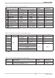

8 Technical data
INPUTS
PROCESS VALUE INPUT INP1
Resolution: > 14 bits
Decimal point: 0 to 3 digits behind the
decimal point
Dig. input filter: adjustable 0,000...9999 s
Scanning cycle: 100 ms
Measured value
correction:
2-point or offset correction
Thermocouples
r Table 2 (page 58 )
Input resistance:
³
1M
W
Effect of source resistance: 1 mV/W
Cold-junction compensation
Maximal additional error: ± 0,5 K
Sensor break monitoring
Sensor current:
£
1
m
A
Configurable output action
Resistance thermometer
r Table 2 (page 58 )
Connection: 2 or 3-wire
Lead resistance: max. 30 Ohm
Input circuit monitor: break and short circuit
Potentiometric transducer 50-30-50 W
Current and voltage signals
r Table 3 (page 58 )
Span start, end of span: anywhere within measuring
range
Scaling: selectable -1999...9999
Linearization: 16 segments, adaptable
with BlueControl
Decimal point: adjustable
Input circuit monitor: 12,5% below span start
(2mA, 1V)
SUPPLEMENTARY INPUT INP2
Resolution: > 14 bits
Scanning cycle: 100 ms
Accuracy: < 0,5 %
Current measuring range
Technical data as for INP1
Potentiometer
r Table 2 (page 58 )
Connection: 3-wire
Lead resistance: max. 30 Ohm
Input circuit monitor: break
CONTROL INPUT DI2/DI3
Configurable as switch or push-button!
Connection of a potential-free contact suitable
for switching “dry” circuits.
Switched voltage: 5 V
Current: 160
m
A
TRANSMITTER SUPPLY UT (OPTION)
Power: 22 mA /
³
18 V
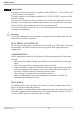
GALVANIC ISOLATION
Safety isolation
Function isolation
KS40-1 burner 32
Power supply
connections
Process value input INP1
Supplementary input INP2
Digital inputs di2, 3
Transmitter supply U
T
Relay outputs OUT 1,2
Relay output OUT3