PMA Prozeß- und Maschinen-Automation GmbH Universal controller for burners KS40-1 burner KS40-1 burner KS40-1 burner Operating manual English expert line 9499-040-66011 Valid from:8473
Description of symbols in the text: on the device: g General information a Follow the operating instructions a General warning l Attention: ESD-sensitive devices © PMA Prozeß- und Maschinen-Automation GmbH • Printed in Germany (0207) All rights reserved. No part of this document may bereproduced or published in any form or by any means without prior written permission from the copyright owner. A publication of PMA Prozeß- und Maschinen Automation P.O.
Contents 1 2 3 3.1 3.2 3.3 3.4 3.5 4 4.1 4.2 Mounting . . . . . . . . . . . . . . . . . . . . . . . . . . . . . . 5 Electrical connections . . . . . . . . . . . . . . . . . . . . . . . 6 Operation. . . . . . . . . . . . . . . . . . . . . . . . . . . . . . 7 Front view. . . . . . . . . . . . . . . . . . . . . . . . . . . . . . 7 Operating level . . . . . . . . . . . . . . . . . . . . . . . . . . . 8 Self-tuning . . . . . . . . . . . . . . . . . . . . . . . . . . . . . 10 Manual tuning . . . . . . . . . . .
KS40-1 burner 4
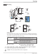
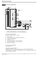
Mounting 1 Mounting 96 (3.78") SP.X 126 125 45 SG Ada +0,8 1. .1 8 ..0 0 .4 ") 11 ") 65 . (4 .0 4 (0 (0 10 max. 60°C min. 0°C max. 95% rel. % 92 ) " .4 (3.62" +0.03) min.48 (1.89") +0,6 (1.77" +0.02) Err F KS 40-1 burner 48 (1.89") Loc 10V i mA/Pt mA/Pt Loc Loc 10V 10V mA/Pt Loc 10V mA/Pt Safety switch Ü or: Ü * * Safety switch: For access to the safety switches, the controller must be withdrawn from the housing.
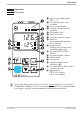
Electrical connections 2 Electrical connections P Option A 1 di2 (2) 1 3 2 4 di3 L N 90...250V 3 5 6 Ut(+) 4 5 6 OUT1 OUT2 7 8 OUT3 g h 9 10 c g b + INP2 100% 11 12 0% 13 0% 14 15 + a + 10V * - 1 2 3 2 100% + 20mA ** - 1 INP1 b c d e f g * Safety switch INP1 (mA i 10V) in position 10V ** Safety switch INP1 (mA i 10V) in position mA/Pt Connection of input INP1 Input for variable x1 (process value) a thermocouple b resistance thermometer (Pt100/ Pt1000/ KTY/ ...
Operation 3 Operation 3.1 Front view 1 1 0 ! " § $ SP.x 125 % OK SG Ada Err 2 3 & 4 5 6 7 8 9 KS 40-1 burner Front view 3 126. è g 2 1 Status of switching outputs OuT.1...
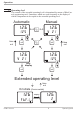
Operation 3.2 Operating level The content of the extended operating level is determined by means of BlueControl (engineering tool). Parameters which are used frequently or the display of which is important can be copied to the extended operating level. Automatic 126 125 È Ì time out Manual 126 iÒ i Ù y 21 È Ì Ù Ò 126 126 y 21 Ù time out 125 È Ì only display Ù Extended operating level time out Errorliste (if error exists) 126 FbF.
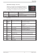
Operation Maintenance manager / Error list With one or several errors, the extended operating level always starts with the error list. Signalling an actual entry in the error list (alarm, error) is done by the Err LED in the display. To reach the error list press Ù twice. Err LED status Signification blinks Alarm due to existing error lit Error removed, Alarm not acknowledged No error,all alarm entries deleted off - SP.
Operation Error status (error status 3 - 9 only with error AdA.H / AdA.
Operation Self-tuning cancellation by the controller: If the Err LED starts blinking while self-tuning is running, successful self-tuning is prevented due to the control conditions. In this case, self-tuning was cancelled by the controller. The controller switches off its outputs (controller output 0%). Acknowledgement procedures in case of unsuccessful self-tuning: 1. Press keys Ù and È simultaneously: The controller continues controlling using the old parameters in automatic mode.
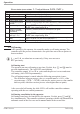
Operation Values Tg and xmax (step change from 0 to 100 %) or Dt and Dx (partial step response) can be used to determine the maximum rate of increase vmax. 100% y Yh 0% t x Tg Xmax y =correcting variable Yh = control range Tu = delay time (s) Tg = recovery time (s) Xmax = maximum process value Vmax= {X {t t Tu Xmax { x = max.
Operation 3.5 Operating structure After supply voltage switch-on, the controller starts with the operating levels. The controller status is as before power off. 126 126 Ù 125 PArA 3 sec. Ì Ù PASS 126 ConF Ù 126 Ì CAL Ì PASS Ù PASS 126 Ù End g PArA - level: At PArA - level, the right decimal point of the upper display line is lit continuously.
Configuration level 4 Configuration level 4.1 Configuration with qUIC At configuration level, the controller function is determined by changing configuration word Con1 . Con1 and the code adjusted for Con1 are displayed alternately on the lower display line. r 126 r Ù r SP.X 125 SG Ada Err 3 sec. PArA Ì ConF r Ù r qUIC r Ù r È Con1 Ì rÙ 123.8 123.8 Con1 1520 A BC D Code signification: 0 1 2 0 Reaction at sensor break as process value higher than set-point.
Configuration level After exit from the configuration level (see page 43, the controller is re-initialized (all display elements are lit) and changes over to normal operation (operating level). g Leading zeros are not displayed (ex.: display 400 with code 0400) Configuration example 1 (code 0400): KS40-1 as a signaller with switch-over contact for 2-stage burner: Measuring range 0...200°C, Resistance thermometer Pt 100, Reaction at sensor break as process value higher than set-point. 123.8 123.
Configuration level Function: 3-point signaller Sd1 ON OFF ON OUT1 Sd2 -X W ON d.SP OUT2 OFF W XW H.1 Limit OUT3 OFF HYS.1 Settings: OUT1: Switch-on point is coupled with the set-point. Switching difference Sd1: in units of phys. quantity. OUT2: Switch-off point is always below the set-point! Adjustment range d.SP : in units of phys. quantity Switching difference Sd2: in units of phys. quantity. Limit value OUT3: With the limit value exceeded, the relay is de-energized. High limit value H.
Configuration level Function: 3-point stepping controller W -X W OFF OUT1 ON ON OUT2 XW XSd -A A SH ON H.1 Limit OUT3 OFF HYS.1 Settings: Controller: SH: in units of phys. quantity Response threshold A: 0,5 w SH Switching difference XSd : 0,06 w SH + 0,08 Actuator travel time tt: 3...9999 s Min.duty cycle: fixed, TEmin = 100 ms Control parameters: Pb1 = 0,01...9999 : in unit of phys. quantity °C or °F (number of digits behind the decimal point is determined by CON1) Ti = 1...
Configuration level 4.2 Configuration without qUIC ( qUIC= OFF) When key Ù is kept pressed during controller supply voltage switch-on, the configuration is switched off with qUIC. Now, all configuration settings are available to the user. For changing back to configuration with qUIC , the two keys Ì È must be kept pressed during controller supply voltage switch-on. a Hereby, the controller is reset to the factory-set default values ! 4.
Configuration level Name Value range Description Default FAIL Behavior at sensor break Controller outputs switched of y = Y2 y=meanoutput.Themaximumpermissibleoutputcanbeadjustedwith parameterYm.H.Topreventdeterminationofinadmissiblevalues,meanvalue formationisonlyifthecontroldeviationislowerthanparameterL.Ym. rnG.L -1999...9999 X0 (low limit range of control) 1 rnG.H -1999...9999 X100 (high limit range of control) 1 Own setting 1 0 1 2 0 100 1 rnG.L and rnG.
Configuration level InP.2 Name Value range I.Fnc 0 2 S.tYP 20 21 22 30 50 51 52 Corr 0 1 2 3 Description Default Function selection of INP2 No function External set-point SP.E (switching -> LOGI/ SP.E) Sensor type selection Pt100 (-200,0 ... 100,0 °C) Pt100 (-200,0 ... 850,0 °C) Pt1000 (-200,0...200,0 °C) 0...20mA / 4...20mA 1 Potentiometer ( 0...160 Ohm) 1 Potentiometer ( 0...450 Ohm) 1 Potentiometer ( 0...
Configuration level Out.1 / 2 / 3 Name Value range O.Act 0 1 Y.1 Y.2 0 1 Lim.1 Lim.2 Lim.3 LP.AL 0 1 0 1 FAi.1 FAi.2 0 1 Description Own setting Default Out.1: 0 Out.2: 0 Out.3: 1 Method of operation of output OUT1 Direct / normally open Inverse / normaly closed Controller output Y1 / Y2 Not active Active Limit 1 / 2 / 3 signal Not active Active Interruption alarm signal (LOOP) Not active Active INP1 / INP2 error signal Not active Active Out.1: 0 / 0 / 0 Out.2: 0 / 0 / 0 Out.
Configuration level Name Value range mAn 0 1 3 4 5 6 C.oFF 0 3 4 5 6 m.Loc 0 3 4 Err.r 5 0 3 4 5 6 SG 0 3 4 P.run 5 0 3 4 di.
Configuration level othr Name Value range Unit 0 1 2 dP C.dEl 0 1 2 3 0...200 Description Default Unit Without unit °C °F Decimal point (max.
Parameter setting level 5 Parameter setting level Cntr Visible Name Value range with qUIC f f Pb1 1...9999 Pb2 1...9999 ti1 1...9999 ti2 1...9999 td1 1...9999 td2 1...9999 t1 0,4...9999 f f t2 0,4...9999 SH 0...9999 f Sd1 0,0...9999 f Sd2 0,0...9999 f d.SP -1999...999 f f tP tt Y.Lo Y.Hi Y2 Y.0 9 0,1...9999 3...9999 -120...120 -120...120 -120...120 -120...120 Ym.H -120...120 L.Ym 0...9999 Description Default Own setting 10 Proportional band 1 (heating) in phys. dimensions (e.g.
Parameter setting level ProG Visible with qUIC Name Value range SP.01 Pt.01 SP.02 Pt.02 SP.03 Pt.03 SP.04 Pt.04 -1999...9999 0...9999 -1999...9999 0...9999 -1999...9999 0...9999 -1999...9999 0...9999 Description Segment end set-point 1 Segment time 1 [min] Segment end set-point 2 Segment time 2 [min] Segment end set-point 3 Segment time 3 [min] Segment end set-point 4 Segment time 4 [min] Default Own setting 100 10 100 10 200 10 200 10 InP.
Parameter setting level 5.1 Input scaling (only visible with qUIC = OFF) When using current or voltage signals as input variables for InP.1 or InP.2, scaling of input and display values at parameter setting level is required. Specification of the input value for lower and higher scaling point is in the relevant electrical unit (mA/ V). phys. quantity OuH.x phys. quantity mA / V OuL.x InH.x mA/V InL.x 5.1.1 Input Inp.1 g Parameters InL.1 , OuL.1, InH.1 and OuH.1 are only visible if ConF / InP.
Calibration level 6 Calibration level g Measured value correction ( CAL) is only visible if ConF / InP.1 / Corr = 1 or 2 and qUIC = OFF is chosen. The measured value can be matched in the calibration menu ( CAL). Two methods are available: Offset correction ( ConF/ InP.1 / Corr =1 ): display standard setting offset correction w possible on-line at the process OuL.1new OuL.1old InL.1 X 2-point correction ( ConF/ InP.
Calibration level Offset correction ( ConF/ InP.1 / Corr =1 ): r SP.X 126 125 run Ada Err r Ù r PArA 3 sec. Ì : CAL r Ù r InP.1 r Ù r InL.1 r Ù r OuL.1 È r Ù Ì r End r Ù InL.1: The input value of the scaling point is displayed. The operator must wait, until the process is at rest. Subsequently, the operator acknowledges the input value by pressing key Ù. OuL.1: The display value of the scaling point is displayed. Before calibration, OuL.1 is equal to InL.1.
Calibration level 2-point correction ( ConF/ InP.1 / Corr =1 ): r SP.X 126 r Ù r 125 run Ada Err 3 sec. PArA Ì : CAL r Ù r InP.1 r Ù r InL.1 r Ù r OuL.1 È r Ù Ì r InH.1 r Ù r OuH.1 È r Ù Ì r End r Ù InL.1: The input value of the lower scaling point is displayed. The operator must adjust the lower input value by means of a process value simulator and confirm the input value by pressing key Ù. OuL.1: The display value of the lower scaling point is displayed. Before calibration, OuL.1 equals InL.1.
Programmer 7 Programmer W,X SP.01 SP.02 SP.03 SP.04 W,X W Pt.01 Pt.02 Pt.03 Pt.04 t Programmer set-up: For using the controller as a programmer, select parameter SP.Fn = 1 in the ConF menu. The programmer is started via one of digital inputs di2..3 or the è key. Which input shall be used for starting the programmer is determined by selecting parameter P.run = 3 / 4 / 5 in the ConF menu accordingly. For assigning the program end as a digital signal to one of the relay outputs, parameter P.
Programmer + Program parameter changing while the program is running is possible. Changing the segment time: Changing the segment time leads to re-calculation of the required gradient. When the segment time has already elapsed, starting with the new segment is done directly, where the set-point changes with a step.
8 Technical data SUPPLEMENTARY INPUT INP2 INPUTS PROCESS VALUE INPUT INP1 Resolution: Decimal point: Dig. input filter: Scanning cycle: Measured value correction: > 14 bits 0 to 3 digits behind the decimal point adjustable 0,000...
OUTPUTS ENVIRONMENTAL CONDITIONS RELAY OUTPUTS OUT1, OUT2 Protection modes Front panel: IP 65 (NEMA 4X) Housing: IP 20 Terminals: IP 00 Contact type: 2 NO contacts with common connection 500 VA, 250 V, 2A at 48...62 Hz, resistive load 6V, 1 mA DC 800.000 duty cycles with max. rating Max. contact rating: Min. contact rating: Operating life (electr.): RELAY OUTPUT OUT3 Contact type: potential-free changeover contact Max.contact rating: 500 VA, 250 V, 2A at 48...62 Hz, resistive load Min.
GENERAL Housing Material: Flammability class: Makrolon 9415 flame-retardant UL 94 VO, self-extinguishing Plug-in module, inserted from the front Safety test Complies with EN 61010-1 (VDE 0411-1): Overvoltage category II Contamination class 2 Working voltage range 300 V Protection class II Certifications Type tested to EN 14597 (replaces DIN 3440) With certified sensors applicable for: w Heat generating plants with outflow temperatures up to 120°C to DIN 4751 w Hot-water plants with outflow temperatures
Technical data Table 1 Thermocouples measuring ranges Type L J K N S R T C D E B* Fe-CuNi (DIN) Fe-CuNi NiCr-Ni Nicrosil/Nisil PtRh-Pt 10% PtRh-Pt 13% Cu-CuNi W5%Re-W26%Re W3%Re-W25%Re NiCr-CuNi PtRh-Pt6% Range -100...900°C -100...1200°C -100...1350°C -100...1300°C 0...1760°C 0...1760°C -200...400°C 0...2315°C 0...2315°C -100...1000°C 0(100)...1820°C -148...1652°F -148...2192°F -148...2462°F -148...2372°F 32...3200°F 32...3200°F -328...752°F 32...4199°F 32...4199°F -148...1832°F 32(212)...
Safety hints 9 Safety hints This unit was built and tested in compliance with VDE 0411-1 / EN 61010-1 and was delivered in safe condition. The unit complies with European guideline 89/336/EWG (EMC) and is provided with CE marking. The unit was tested before delivery and has passed the tests required by the test schedule. To maintain this condition and to ensure safe operation, the user must follow the hints and warnings given in this operating manual.
Safety hints MAINTENANCE, REPAIR AND MODIFICATION The units do not need particular maintenance. Warning a When opening the units, or when removing covers or components, live parts and terminals may be exposed. Before starting this work, the unit must be disconnected completely. After completing this work, re-shut the unit and re-fit all covers and components. Check if specifications on the type label must be changed and correct them, if necessary.
Safety hints 9.1 Resetting to factory setting In case of faultyconfiguration, KS4x-1 can be reset to the default condition. For this, the operator must keep the keys increment and decrement pressed during power-on. Then, press key increment to select YES. Confirm factory resetting with Enter and the copy procedure is started (display COPY). Afterwards the device restarts. 1 2 3 ÌÈ + Power on È Ù SP.x FAC torY 1. run SP.x Ada Err FAC no run Ada Err SP.x FAC YES run SP.
Index 0-9 M 2-point correction . . . . . . . . . . . . . 27 Maintenance manager . . . . . . . . . . . . 9 Manual tuning . . . . . . . . . . . . . 11 - 12 Mounting . . . . . . . . . . . . . . . . . . 5 C Calibration (CAL) . . . . . . . . . . . . . 27 Calibration level (CAL) . . . . . . . . 27 - 29 Configuration with QUIC . . . . . . 14 - 17 Configuration without QUIC . . . . . . . 18 Control inputs di1, di2, di3 Technical data . . . . . . . . . . . . . . 32 Current signal measuring range . . . . . .
Subject to alterations without notice Änderungen vorbehalten Sous réserve de toutes modifications © PMA Prozeß- und Maschinen-Automation GmbH P.O.B.