
Instruction Manual

73
4 Configuration parameters
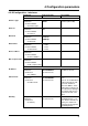
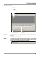
4.2.7 Configuration - Outputs (extra code)
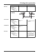
Storage cycle:
Timed operation
Configuration
➔ Recording
➔ Timed operation
➔ Storage cycle
1—5 — 32767s v Chapter 2.7 “Operating
modes”
Chapter 2.8 “Storing
data”
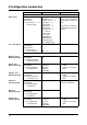
Control signal:
Event operation
Configuration
➔ Recording
➔ Event operation
➔ Control signal
Off,
Bin. inp. 1 — 4,
Logic channel 1 — 6,
Low alarm 1 — 6,
Low comb.al.,
High alarm 1 — 6,
High comb.al.,
Count/Int/Al 1 — 6,
C/i. comb.al.,
Comb. alarm,
CF inserted,
IntMemAlmCF,
IntMemAlmSer,
MemAlmCFcard,
Error, Modbus flag,
If the configured signal is
active, the instrument will
switch to event operation.
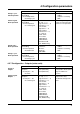
Stored value:
Event operation
Configuration
➔ Recording
➔ Event operation
➔ Stored value
Average val.,
Instant val.,
Minimum,
Maximum,
Peak value
v Chapter 2.7 “Operating
modes”
Chapter 2.8 “Storing
data”
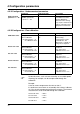
Storage cycle:
Event operation
Configuration
➔ Recording
➔ Event operation
➔ Storage cycle
1—5 — 32767s v Chapter 2.7 “Operating
modes”
Chapter 2.8 “Storing
data”
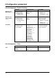
Parameter Value/Selection Description
Action of
outputs
Configuration
➔ Outputs
➔ Relay K1 — K3,
➔ Action
Off,
make (SPST-NO),
break (SPST-NC)
As standard, relay K1 is
configured as break (SPST-
NO), K2 and K3 are
inactive.
Control signal:
Outputs
Configuration
➔ Outputs
➔ Relay K1 — K3,
➔ Control signal
Off,
Bin. inp. 1 — 4,
Logic channel 1 — 6,
Low alarm 1 — 6,
Low comb.al.,
High alarm 1 — 6,
High comb.al.,
Count/Int/Al 1 — 6,
C/i. comb.al.,
Comb. alarm,
CF inserted,
IntMemAlmCF,
IntMemAlmSer,
MemAlmCFcard,
Error, Modbus flag
The configured signal is
output to the relay.
The default setting for K1 is
Error.
Parameter Value/Selection Description