
Instruction Manual


2 Device description
22
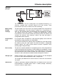
Logic module You also have up to 6 channels available as logic channels.
As is the case with all the other digital signals, the calculated digital (Boolean)
values can be used for different functions:
- recording in the event traces,
- as a control signal for display switch-off,
- clock time synchronization,
- operating time counter,
- externally controlled counters / integrators
- counter/integr. reset
- event operation and key inhibit,
- for output to a relay and
- as count input for a counter.
The following variables are used for the formulae:
- binary inputs
- logic channels
-alarms
-errors
- Modbus flag (signal via interface)
-TRUE
-FALSE
- device-specific data (only after consultation with the manufacturer)
These functions can be used for the formulae:
-! (NOT)
-& (AND)
-| (OR)
-^ (XOR)
- / (rising edge)
- \ (falling edge)
-( (open bracket)
-) (close bracket)
H
For further information, refer to
Chapter 5.9 “Math/logic”