
Instruction Manual

15
2 Device description
2.4 Digital signals (event traces)
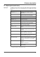
Signal types In addition to the four binary inputs (extra code), digital signals generated by
the instrument itself can also be displayed in the six digital traces (event
traces):
signal Description
Binary input 1 — 4 Four binary inputs available as hardware
(extra code)
Logic channel 1 — 6 Channels which are created by using the math
and logic module (extra code required)
Low alarm 1 — 6 Underrange of the channels
Low combination alarm OR linkage of all low alarms
High alarm 1 — 6 Overlimit of channels
High combination alarm OR linkage of all high alarms
Counter/integrator alarm 1 — 6 Limit infringements of counter and
integrator channels (extra code required)
Counter/integrator combination
alarm
OR linkage of all counter/integrator
alarms (extra code required)
Combination alarm OR linkage of all low, high and counter/inegrator
alarms
CF card inserted The signal is set when a CF card is inserted in the
instrument. It remains active until the card is
removed.
Int. mem. alarm/CF card The alarm is triggered when the internal storage
memory available for read-out via the CF card
card has fallen below a certain value
1
.
1
The limit for all memory alarms is the same, and is set by the parameter
Configuration Device data Memory alarm.
Int. mem. alarm/serial The alarm is triggered when the internal storage
memory available for read-out via the interface
has fallen below a certain value
1
.
Mem. alarm/CF card The alarm is triggered when the storage memory
available on the CF card that has been plugged in
falls below a certain value
1
, or no CF card is
plugged in.
Error Alarm when the battery is empty, or the time has
to be set.
Chapter 3.7 “Device info”
MODbus flag Control flag, which can be activated through one
of the interfaces.