
Instruction Manual

10 Electrical connection
124
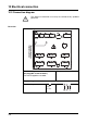
Terminal assignment Diagram
Setup interface (included in delivery)
The setup interface can
be found on the front of
the instrument, behind
the cover for the
CompactFlash
memory card.
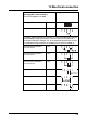
Interfaces (extra code)
RS232
9-pole SUB-D socket
20 2 RxD receive data
3 TxD transmit data
5 GND ground
RS485
9-pole SUB-D socket
20 3 TxD+/RxD+
transmit/receive data +
5 GND ground
8TxD-/RxD-
transmit/receive data -
Ethernet
RJ45 socket
21
1TX+ transmit data +
2TX- transmit data -
3 RX+ receive data +
6 RX- receive data -
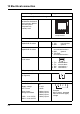
Relay outputs (extra code)
Relays K1, K2, K3
(changeover)
30, 31, 32
Binary inputs (extra code)
Supply voltage
24V / 50mA
Binary inputs,
voltage-controlled
LOW = -3 to +5V DC
HIGH = 12 to 30V DC
33
6 +24V
5 GND
4 binary input 1
3 binary input 2
2 binary input 3
1 binary input 4
Setup interface
8
1
Example:
binary input 4, operated
from the internal supply
voltage