
Manual


1
/
4
-DIN,
1
/
8
-DIN &
1
/
16
- DIN Controllers & Indicators - Product Manual
59305, Issue 7 – March 2014 P6010 & P8010 Model Group Page 103
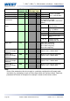
Parameter
Legend
for 1 sec
followed
by
Set
Value
Adjustment Range &
Description
Default
Value
When
Visible
Units
Display
(
1
/
8
Din
Only)
Output 2 Usage
As for Output 1 usage
or
is not
empty
Output 2 PV
Retransmit Type
0 to 5 V DC output 1
=
0 to 10 V DC output
2 to 10 V DC output
0 to 20 mA DC output
4 to 20 mA DC output
Retransmit
Output 2 Scale
maximum
to
Display value where output is maximum
Range
max
=
Retransmit
Output 2 Scale
minimum
to
Display value where output is minimum
Range
min
=
Output 2 TxPSU
voltage level
0 to 10VDC transmitter power supply
output in 0.1V steps*
=
Output 3 Usage
As for Output 1 usage
or
is not
empty
Output 3 PV
Retransmit Type
0 to 5 V DC output 1
=
0 to 10 V DC output
2 to 10 V DC output
0 to 20 mA DC output
4 to 20 mA DC output
Retransmit
Output 3 Scale
maximum
to
Display value where output is maximum
Range
max
=
Retransmit
Output 3 Scale
minimum
to
Display value where output is minimum
Range
min
=
Output 3 TxPSU
voltage level
0 to 10VDC transmitter power supply
output in 0.1V steps*
=
Output 4 Usage
Alarm output options as for Output 1
usage (Linear retransmit and PSU not
possible)
=
Output 5 Usage
Alarm output options as for Output 1
usage (Linear retransmit and PSU not
possible)
=