
Manual


1
/
4
-DIN,
1
/
8
-DIN &
1
/
16
- DIN Controllers & Indicators - Product Manual
Page 100 P6010 & P8010 Model Group 59305, Issue 7 – March 2014
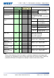
Parameter
Legend
for 1 sec
followed
by
Set
Value
Adjustment Range &
Description
Default
Value
When
Visible
Units
Display
(
1
/
8
Din
Only)
Scale Range
Upper Limit
Scale Range Lower Limit +100 to Range
Max
Linear
= 1000
°C/°F =
max
range
Always
Scale Range
Lower Limit
Range Min. to Scale range Upper Limit -
100
Linear
= 0
°C/°F =
min
range
Always
Decimal point
position
Decimal point position in non-
temperature ranges.
0 = XXXX
1 = XXX.X
2 = XX.XX
3 = X.XXX
= mV, V
or mA
Linear Range
Engineering
Units Display
(Blank), = °C or = °F
For use where linear inputs
represent temperature.
Available on
1
/
8
Din units only.
1
/
8
Din
only.
= mV, V
or mA
°
°
Multi-Point
Scaling
disabled or
enabled
Always
Alarm 1Type
Process High Alarm
Always
Process Low Alarm
No alarm
Process High
Alarm 1 value*
Range Min. to Range Max.
Parameter repeated in Setup Mode
Range
Max.
=
if
alarm
1 only
or
Process Low
Alarm 1 value*
Range Min. to Range Max
Parameter repeated in Setup Mode
Range
Min.
=
Alarm 1
Hysteresis*
1 LSD to 100% of span (in display units)
on “safe” side of alarm point.
Parameter repeated in Setup Mode
is not
Alarm 2 Type
As for alarm 1 type
Always
Process High
Alarm 2 value*
Range Min. to Range Max.
Parameter repeated in Setup Mode
Range
Max.
=
Process Low
Alarm 2 value*
Range Min. to Range Max.
Parameter repeated in Setup Mode
Range
Min.
=
Alarm 2
Hysteresis*
1 LSD to 100% of span (in display units)
on “safe” side of alarm point.
Parameter repeated in Setup Mode
is not