
User Manual

Curtis 1268 Manual, Rev. D 7
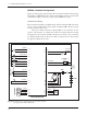
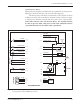
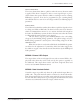
F1
B- B+M-
F2
STATUS
LED
CABLE-FREE ZONE
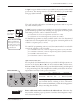
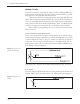
A 6-pin low power Molex connector is provided for the interface with the Hall
speed sensor. The mating connector is a Molex Mini-Fit Jr. p/n 39-01-2065
using type 5556 terminals.
J2-1,2,3 (not used)
J2-4 ground
J2-5 input
J2-6 +15V
Power cables must not be routed over the indicated area. Otherwise they
may interfere with the proper operation of sensitive electromagnetic compo
-
nents located underneath.
The +15V supply should only be used with the speed sensor and not to power
any other external systems.
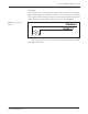
A 4-pin low power connector is provided for an optional programmer. A com-
plete handheld programmer kit, including the appropriate connecting cable
with mating connector, can be ordered from Curtis:
p/n 168961101 for the User Programmer (model 1311-1101)
p/n 168962101 for the OEM Programmer (model 1311-4401).
If a handheld programmer is already available (such as the now discontinued
1307) but has an incompatible cable, the appropriate connecting cable can be
ordered as a separate part: p/n 16185.
If a 1314 PC programming station is used, the 1309 interface box and cable
connect the computer to the controller:
p/n 117465704 1314-1101, 1314 PC Programming Station (User) CD-ROM
p/n 117465707 1314-4401, 1314 PC Programming Station (OEM) CD-ROM
p/n 16994001 1309 Interface Box
p/n 16185 Molex cable for 1309 Interface Box.
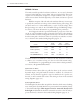
High Current Connections
Five tin-plated solid aluminum bus bars are provided for the high current con-
nections to the battery
(B+ and B-), the motor armature (M-), and the motor
field (F1 and F2). These bus bars incorporate threaded mounting studs designed
to accept mounting bolts. This simplifies the assembly and reduces the mount
-
ing hardware necessary for the power connections.
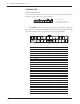
SIZE MAX DEPTH QTY MAX TORQUE
Field studs M6 × 1 5/8" 2 16.3 N·m (12 ft-lbs)
Power studs M8 × 1.25 3/4" 3 20.0 N·m (15 ft-lbs)
Exceeding these specifications could damage the bus
bars’ internal threads, resulting in loose connections.
We recommend maximum possible thread engagement:
always exceeding three threads.
2 — INSTALLATION & WIRING: Controller
456
123
34
12
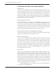
J3
J2
J3-1 Rx Data
J3-2 B-
J3-3 Tx Data
J3-4 +15V
☞
C A U T I O N
note: The 1311 hand-
held programmer has
been superseded; if you
are using a more recent
model, please refer to its
documentation.