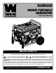
MODEL GN9500X 9500W PORTABLE GENERATOR Instruction Manual NEED HELP? CONTACT US! Have product questions? Need technical support? Please feel free to contact us: 1-800-232-1195 (M-F 8AM-5PM CST) TECHSUPPORT@WENPRODUCTS.COM IMPORTANT: Your new tool has been engineered and manufactured to WEN’s highest standards for dependability, ease of operation, and operator safety. When properly cared for, this product will supply you years of rugged, trouble-free performance.
CONTENTS WELCOME 3 Specifications.................................................................................................... 3 Introduction...................................................................................................... 4 SAFETY 5 Safety Information............................................................................................ 5 Generator Safety Warnings...............................................................................
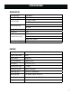
SPECIFICATIONS GENERATOR Rated Wattage 7500 Watts Surge Wattage 9500 Watts Rated Voltage Rated Amperage AC: 120V / 240V DC: 12V AC: 60A / 30A DC: 8.3A Phase Single Frequency 60Hz Length: 27.3 Inches Product Dimensions Width: 20.8 Inches Height: 22.2 Inches Product Net Weight 194 lbs (88 KG) ENGINE Engine Type 4 Stroke, OHV, Single Cylinder with Forced Air Cooling System Engine Displacement 420cc Engine Speed 3600 RPM Fuel Tank Capacity 6 gallons (23 L) Oil Capacity 37.2 fl. oz. (1.
INTRODUCTION Thanks for purchasing the WEN 9500-Watt Portable Generator. Refer to the illustration below for the location of the serial number on the side of the engine. Record the generator information in the spaces provided below. If assistance for information or service is required, please contact customer service by calling 1-800-232-1195, M-F 8-5 CST; you will be asked to provide the following generator information when calling.
SAFETY INFORMATION WARNING! Before operating the generator, make sure to read all safety warnings and all instructions. Failure to follow the warnings and instructions may result in electric shock, fire or serious injury. SAFETY INTRODUCTION Safety is a combination of common sense, staying alert, and knowing how your tool works. This manual contains important information regarding the generator’s potential safety concerns, as well as preparation, operation, and maintenance instructions.
GENERATOR SAFETY WARNINGS DANGER! CARBON MONOXIDE Using a generator indoors CAN KILL YOU IN MINUTES. Generator exhaust contains carbon monoxide (CO). This is a poison gas you cannot see or smell. If you can smell the generator exhaust, you are breathing CO. But even if you cannot smell the exhaust, you could be breathing CO. NEVER use a generator inside homes, garages, crawl spaces, or other partially enclosed areas. Deadly levels of carbon monoxide can build up in these areas.
GENERATOR SAFETY WARNINGS WARNING! Do not let comfort or familiarity with the product replace strict adherence to product safety rules. Failure to follow the safety instructions may result in serious personal injury. OPERATING ENVIRONMENT 1. Using a generator indoors can kill you in minutes. Only use a generator outside and far away from windows, doors and vents. 2. Do not smoke near the generator. 3. Do not operate near open flame, heat, or flammable materials.
GENERATOR SAFETY WARNINGS WARNING! Do not let comfort or familiarity with the product replace strict adherence to product safety rules. Failure to follow the safety instructions may result in serious personal injury. TO MAXIMIZE THE LIFESPAN OF YOUR GENERATOR: We recommend running your generator at least once a month for 20 to 30 minutes. Start the generator according to the instructions and plug a small load in to make sure the outlet is producing electricity.
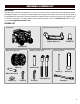
UNPACKING & PACKING LIST UNPACKING With the help of a friend or trustworthy foe, such as one of your in-laws, carefully remove the generator from the packaging and place it on a sturdy, flat surface. Make sure to take out all contents and accessories. Do not discard the packaging until everything is removed. Check the packing list below to make sure you have all of the parts and accessories.
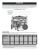
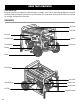
KNOW YOUR GENERATOR TOOL PURPOSE Generators provide you with power when and where you need it most. Refer to the following diagrams to become familiarized with all the parts and controls of your Generator. The components will be referred to later in the manual for assembly and operation instructions.
KNOW YOUR GENERATOR CONTROL PANEL 1 13 2 3 4 14 5 12 11 10 9 8 1. Key Start ON, OFF. START 2. Pairing Light Indicates pairing of the remote to your generator. See "USING THE REMOTE START FUNCTION" on page 20. 3. 12V DC Outlet 6 7 8. AC Circuit Breaker (30A) 9. AC 120V NEMA TT-30R RV Outlet 10. AC 120V NEMA 5-20V Duplex Outlet 11. DC Circuit Breaker (10A) 4. 5-20R Duplex Circuit Breakers (20A) 12. Remote Power Button Press to reset remote pairing.
ASSEMBLY & ADJUSTMENTS Fig. 1 WARNING! Do not plug in or turn on the tool until it is fully assembled according to the instructions. Read through and become familiarized with the following procedures of handling and adjusting your tool. Failure to follow the safety instructions may result in serious personal injury. 5 4 INSTALLING THE WHEELS 2 1 1. Prepare a set of blocks on level ground (a 4×4 block of wood works well). Place the generator on the blocks. 3 2. Place the wheel axle pin (Fig.
GENERATOR PREPARATION The following section describes the necessary steps to prepare the generator for use. If you are unsure about how to perform any of the steps, please call 1-(800) 232-1195 M-F 8-5 CST for customer service. Failure to perform these steps properly can damage the generator or shorten its life. STEP 1 - ADD / CHECK OIL The generator is shipped without oil. User must add the proper amount of oil before operating the generator for the first time.
GENERATOR PREPARATION STEP 1 - ADD / CHECK OIL (CONTINUED) Fig. 7 For subsequent operation, the oil level should be checked before each use, or after every 8 hours of operation. The generator is equipped with a low-oil sensor and will not start without a sufficient amount of oil. To check oil level (before every subsequent start): 1. Place the generator on a level surface. Make sure the engine is OFF before adding or checking oil. 2. Remove and wipe the dipstick with a clean rag. 3.
GENERATOR PREPARATION STEP 2 - ADD / CHECK FUEL WARNING! RISK OF EXPLOSION. HIGHLY FLAMMABLE: This generator may emit highly flammable and explosive gasoline vapors, which can cause severe burns or even death, if ignited. A nearby open flame can lead to explosion even if not directly in contact with gasoline. • Do not operate near open flame, heat, or any other ignition source. Do not smoke near the generator. • Always operate on a firm, level surface. • Always turn generator off before refueling.
GENERATOR PREPARATION STEP 3: CONNECT THE BATTERY WARNING! Battery gives off explosive hydrogen gas. • Keep battery away from spark, flame, or cigarette. • Do not connect or disconnect battery while generator is running. • Service or use battery only in well ventilated areas. WARNING! Battery contains sulfuric acid. Battery acid is poisonous. Tilting the generator with the battery installed can cause battery acid to spill. • Wear protective clothing and eye wear when servicing battery.
GENERATOR PREPARATION STEP 4 - GROUND THE GENERATOR Fig. 10 To reduce the risk of electric shock and to maximize safety, the generator should be properly grounded. Ground generator by tightening grounding nut (Fig. 10 - 1) on the front control panel against a grounding wire. A generally acceptable grounding wire is a No. 12 AWG (American Wire Gauge) stranded copper wire. 1 This grounding wire should be connected at the other end to a copper, brass, or steel grounding rod that is driven into the earth.
STARTING YOUR GENERATOR Before starting the generator, make sure you have read and performed the steps in the “Generator Preparation” section of this manual. If you are unsure about how to perform any of the steps in this manual please call 1-(800) 232-1195 M-F 8-5 CST for customer service. DANGER! CARBON MONOXIDE Using a generator indoors CAN KILL YOU IN MINUTES. Generator exhaust contains carbon monoxide (CO). This is a poison gas you cannot see or smell.
STARTING YOUR GENERATOR BEFORE STARTING THE GENERATOR 1. Verify that generator is outside on a dry, level surface with at least two feet of clearance on all sides. Fig. 11 2. To maximize safety, check that the generator is properly grounded (see “Ground the Generator”). 3. Check there is sufficient level of oil in the crankcase. Add oil if necessary (see “Add / Check Oil”). 4. Make sure there is sufficient level of gasoline in the fuel tank. Add fuel if necessary (see “Add / Check Fuel”). Fig. 12 5.
STARTING YOUR GENERATOR USING THE REMOTE-START FUNCTION Your generator comes with a remote-start function, enabling you to (what else?) start your generator remotely. Fig. 13 1 4 Your generator and the included remote have been paired at the factory, and you can use the remote immediately. 2 NOTE: in order for the remote start function to work properly, you must be within 164 ft (50 m) of the generator.
STARTING YOUR GENERATOR UNPAIRING THE REMOTE AND GENERATOR 1. Insert the engine switch key and turn the engine switch on the control panel (Fig. 13 - 1) to ON. 2. Press the REMOTE POWER button (Fig. 13 - 3) on the control panel. 3. Press and hold REMOTE PAIRING button (Fig. 13 - 2) on control panel until PAIRING LIGHT (Fig. 13 – 4) turns on. 4. Press the STOP button (Fig. 14 – 2) on the remote control once. The PAIRING LIGHT will turn off, then back on. 5.
USING YOUR GENERATOR CALCULATING THE WATTAGE OF YOUR DEVICE(S) Connect electrical devices running on AC current according to their wattage requirements. Calculate the total running wattage and starting wattage of the device(s) you wish to connect, and MAKE SURE that they are within the capacity of your generator and the capacity of each individual outlet.
USING YOUR GENERATOR CALCULATING THE WATTAGE OF YOUR DEVICE(S) - CONTINUED The chart below serves as a reference for the estimated wattage requirements of common electrical devices. However, do not solely rely on this chart - all electronics and appliances are built differently. Always check the wattage listed on the electrical device before consulting this chart.
USING YOUR GENERATOR CONNECTING ELECTRICAL DEVICES CAUTION! Become familiar with the functions and capacity of each component on the control panel before connecting electrical devices. Do not overload generator or individual panel receptacles. Do not connect 50Hz or 3-phase loads to the generator. Follow the steps below to properly connect your device(s) to the generator: 1. Before connecting electrical devices, allow the generator to run for a few minutes to stabilize the speed and voltage output. 2.
USING YOUR GENERATOR SOME NOTES ABOUT POWER CORDS Long or thin cords can drain the power provided to an electrical device by the generator. When using such cords, allow for a slightly higher rated wattage requirement by the electrical device. Device Requirements Amps 2.5 5 7.5 10 15 20 25 30 40 Watts (120V) 300 600 900 1200 1800 2400 3000 3600 4800 *NR = Not Recommended Max.
USING YOUR GENERATOR CO SENSOR INFORMATION The CO Watchdog carbon monoxide monitoring system (Fig. 16 - 1) measures the accumulation of poisonous CO gas while the generator is running. If the level of CO gas gets too high, the CO Watchdog system will automatically shut down the generator. This system is not a substitute for an indoor CO alarm. Whenever the CO Watchdog system shuts down the generator, the LED on the generator control panel (Fig.
SHUTTING OFF YOUR GENERATOR CAUTION! Unplugging running devices can cause damage to the generator. Never stop the engine with electrical devices connected and running. WARNING! Allow the generator to cool down before touching areas that become hot during use. CAUTION: Allowing gasoline to sit in the fuel tank for long periods of time can make it difficult to start the generator in the future. Never store the generator for extended periods of time (over 2 months) with fuel in the fuel tank.
MAINTENANCE Proper routine maintenance of the generator will help prolong the life of the machine. Please perform maintenance checks and operations according to the schedule in Table 4. CAUTION! Never perform maintenance operations while the generator is running. Before maintaining or servicing the generator, turn OFF the generator, disconnect all devices and allow the generator to cool down.
MAINTENANCE CHECKING / ADDING OIL Fig. 19 Check the oil level before each use and every 8 hours of operation (refer to page 27, Table 4). The oil capacity of the generator engine is 37.2 fl. oz. (1.1 L). Add oil when the oil level is low. For the proper type and weight of oil refer to page 13, Fig. 4. This is a critical step for proper engine starting. The generator is equipped with a low-oil shutdown feature to protect it from running without oil.
MAINTENANCE DRAINING THE CARBURETOR Fig. 20 Drain the carburetor after every use and before storing the generator (refer to page 28, Table 4). Draining the carburetor can help prevent build-up and blockages caused by stagnant fuel inside of the carburetor. 1. Prepare an approved gasoline-storage container under the carburetor to collect drained fuel. Close the fuel valve (Fig. 20). 2. The carburetor can be accessed from the backside of the generator between the engine and air filter.
MAINTENANCE SPARK ARRESTOR MAINTENANCE Inspect and clean the spark arrestor every 100 hours of operation (refer to page 28, Table 4). The spark arrestor is located outside the muffler, which gets very hot during operation. Allow the engine to cool completely before servicing the spark arrestor. Fig. 23 Spark Plug Boot Cylinder Assembly 1. Remove the two Phillips-head screws that secure the spark arrestor to the muffler (Fig. 23). 2. Remove the spark arrestor screen. 3.
MAINTENANCE DRAINING THE FUEL TANK Fig. 26 Drain and clean the fuel tank each year, or before storing the generator for longer than two months. 1. Prepare an approved gasoline-storage container to collect the drained fuel. Place it near the fuel valve. 2. Turn the fuel valve (Fig. 26) to the OFF position. 3. Locate the fuel line (Fig. 27 - 1) between the fuel valve and the carburetor. Disconnect the fuel line from the fuel valve. NOTE: A small amount of fuel may leak from the fuel line during removal. 4.
MAINTENANCE BATTERY MAINTENANCE/STORAGE The battery (part no.GN9500-059) shipped with the generator has been fully charged. The battery will receive charge when the engine is running. Remember to run the generator once a month for 20-30 minutes to charge the battery. A charged battery will allow you to start the generator using the electric start switch during your next time of need. If the battery is out of charge, you can still manually start the generator using the recoil start.
TRANSPORTATION & STORAGE TRANSPORTING THE GENERATOR To prevent fuel spillage when transporting, be sure to perform the following: 1. Tighten the fuel cap. 2. Flip the engine switch to the OFF position. 3. Drain the fuel tank if possible. Refer to section, “Draining the Fuel Tank.” 4. Keep the generator upright. Never place the generator on its side or upside down - doing so could damage the internal components of the generator and make it difficult to start. WARNING! Avoid direct sunlight inside a vehicle.
TROUBLESHOOTING GUIDE WARNING! Stop using the generator immediately if any of the following problems occur or risk serious personal injury. If you have any questions, please contact customer service at 1-800-232-1195 (M-F 8-5 CST), or email techsupport@wenproducts.com. PROBLEM POSSIBLE CAUSE 1. Engine switch is set to OFF. 1. Set engine switch to ON. 2. Fuel valve is turned to OFF. 2. Turn fuel valve to ON. 3. Oil is low. 4. Engine is out of fuel. Engine will not start. 5.
TROUBLESHOOTING GUIDE WARNING! Stop using the generator immediately if any of the following problems occur or risk serious personal injury. If you have any questions, please contact customer service at 1-800-232-1195 (M-F 8-5 CST), or email techsupport@wenproducts.com. 1. Generator is overloaded. Generator runs but does not support all electrical devices connected. 2. Short circuit in one of the devices. 3. Air filter is dirty 1.
W/Bl Bl/R Bl/W Yellow Blue Green Y Bu G Gray Gr G/W Pink Brown P Br Y/W Orange Or R/G R/Y Bu/W Red White R W Y/G Bl/Y Red / Green Red / Yellow Green / White Yellow / White Blue / White Black / White Black / Red Yellow / Green White / Black Black / Yellow Wire Color Black Bl WIRING DIAGRAM 37
EXPLODED VIEW & PARTS LIST GENERATOR 38
EXPLODED VIEW & PARTS LIST GENERATOR NO. PART NO. 1 GN9500-001 2 56500-004 3 GN9500-003 4 GN9500-004 5 56500-007 6 GN9500-006 7 GN9500-007 8 GN9500-008 9 56500-010 10 GN9500X-010 11 56500-060 12 GN9500-012 13 56500-047 14 56500-052 15 GN9500-015 16 GN9500-016 17 GN9500-017 18 GN9500X-018 19 GN9500-019 20 GN9500-020 21 GN9500-021 22 GN9500-022 23 GN9500-023 24 GN9500X-024 25 GN9500-025 26 GN9500-303.
EXPLODED VIEW & PARTS LIST ENGINE 40
EXPLODED VIEW & PARTS LIST ENGINE NO. 1 2 3 PART NO.
EXPLODED VIEW & PARTS LIST ENGINE 42 NO. 65 66 67 68 69 70 PART NO. GN9500-165 GN9500-166 GN9500-167 GN9500-168 GN9500-169 GN9500-170 QTY.
EXPLODED VIEW & PARTS LIST CONTROL PANEL NO. 1 2 3 PART NO. GN9500-301 GN9500X-302 GN9500-303 4 GN9500-304 5 6 7 GN9500-302 GN9500-306 GN9500-307 8 GN9500-308 9 GN9500-309 10 GN9500-310 DESCRIPTION QTY. DC Breaker, 10A 1 CO Sensor LED 1 Engine Switch 1 Remote Start Pairing 1 Light Remote Reset Button 1 DC 12V Outlet 1 AC Breaker, 20A 2 AC 120V NEMA 5-20R 2 duplex Outlet AC Breaker, 30A 2 AC 120V NEMA 1 TT-30R RV Outlet NO. 11 12 13 14 15 16 17 N.P. N.P. PART NO. DESCRIPTION QTY.
WARRANTY STATEMENT WEN Products is committed to building tools that are dependable for years. Our warranties are consistent with this commitment and our dedication to quality. LIMITED WARRANTY OF WEN PRODUCTS FOR HOME USE GREAT LAKES TECHNOLOGIES, LLC (“Seller”) warrants to the original purchaser only, that all WEN consumer power tools will be free from defects in material or workmanship during personal use for a period of two (2) years from date fessional or commercial use.