
Use and Care Manual


14
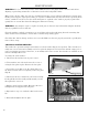
MAINTENANCE
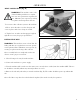
WARNING: For your own safety, turn the switch OFF and remove the plug from the electrical outlet before
adjusting or performing maintenance or lubrication work on the belt/spindle sander.
Before using, check to make sure parts are not damaged, missing, or worn. Check for alignment of moving parts,
binding of moving parts, improper mounting, or any other conditions that may affect the sander operation. If any
of these conditions exist, do not use the sander until parts are replaced or the sander is properly repaired. Fre-
quently blow or vacuum dust from all sanding parts and motor housing.
WARNING: Any attempt to repair or replace electrical parts on this tool may be hazardous. Repairs should be
done by a qualified service technician.
Clean the machine regularly, vacuuming excess wood chips and saw dust and wiping down the remaining dust
with a cloth. If resin accumulates, clean it with a resin-dissolving cleaning agent.
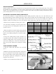
Check the drive belt for damage and wear once a month. Make sure that it is properly tensioned, especially after
times of heavy usage.
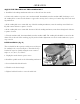
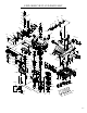
CHANGING MOTOR BRUSHES
This sander has a permanent magnet motor that uses carbon brushes (Fig. O) for operation. These brushes nor-
mally wear out over time and eventually need to be replaced. Symptoms of worn brushes include surging or lost
power, inconsistent operation of the motor, or an inability of the motor to start. New brushes are available on our
website at WENproducts.com
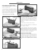
To change the motor brushes:
1. Disconnect the machine from its power source.
2. Turn machine on its side and remove the screws se-
curing the base plate in place. Remove the base plate.
3. Loosen the screws that secure the clamp plates over
the brush assembly. Do not completely remove the plate
(Fig. P).
4. Disconnect the wires attached to your brush assembly.
Gently pull the brush assembly straight toward you and
then upwards to remove it.
5. Replace motor brush assembly. Reconnect the wires
and tighten the clamp plate back into place.
6. Repeat these steps 3 to 5 with the other brush assem-
bly.
7. Re-install and tighten the base plate.
Fig. O
Fig. P