
Use and Care Manual

7
ASSEMBLY AND ADJUSTMENTS
NOTE: Before making any adjustments check that the pow-
er switch is in the OFF position and that the plug is disconnected
from the power source.
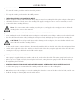
SANDING BELT TABLE
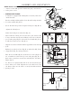
This machine is equipped with a tilting table secured by a lock lever.
To install the table:
1. Pass the sanding belt through the slot on the table and position the
table on the machine (Fig. B - 1).
2. Secure the table into position using the locking lever (Fig. B - 2).
To tighten the locking lever:
1. Gather the locking lever and washer (Fig. C).
2. Disassemble the locking lever into the three parts shown in Fig.
D. Using a 3mm hex wrench (not included), remove the socket head
cap screw with spring (Fig. D - 3) from the lever handle (Fig. D - 2).
This will release the lever base (Fig. D - 1).
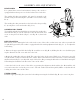
3. Align the slot in the belt table with the tapped hole in the housing.
(Fig. E).
4. By hand, screw the lever base (Fig. D - 1) and washer (Fig. C) into
the tapped hole (Fig. E) , turning clockwise.
5. Place the lever handle (Fig. D - 2) onto the lever base (Fig. D - 1).
Then, re-install the socket head cap screw and spring (Fig. D - 3).
Tighten using a 3mm hex wrench (not included). See the final as-
sembly in Fig. F.
Note: The lever is spring-loaded, and can be loosened and re-posi-
tioned to allow you to make adjustments to the table bevel, as de-
sired. Always make sure the table is securely locked down before
beginning to sand.
2
Fig. B
1
3
4
5
6
Fig. C Fig. D
Fig. E
1
2
3
Washer
Belt Table
Tapped
Hole
Lever
Base
Washer
Fig. F
Belt Table
Tapped
Hole
Locking
Lever
Assembly