Oscillating Spindle Sander Model: 6510
Table of Contents Technical data…………………………………………………………….. General safety rules………………………………………………………. Specific safety rules for the spindle sander………………………………. Electrical information…………………………………………………….. Know your spindle sander………………………………………………... Assembly and adjustments……………………………………………….. Operation…………………………………………………………………. Maintenance………………………………………………………………. Troubleshooting...………………………………………………………… Exploded view and parts list ……………………………………………... Warranty…………………………………………………………………..
General safety rules Safety is a combination of common sense, staying alert and knowing how your oscillating spindle sander works. SAVE THESE SAFETY INSTRUCTIONS. WARNING: To avoid mistakes that could cause serious injury, do not plug in the sander until the following steps have been read and understood. 1. READ and become familiar with this entire instruction manual. LEARN the tool’s applications, limitations, and possible hazards. 2. AVOID DANGEROUS CONDITIONS.
General safety rules (continued) 13. NEVER LEAVE A RUNNING TOOL UNATTENDED. Turn the power switch to OFF. Do not leave the tool until it has come to a complete stop. 14. NEVER STAND ON A TOOL. Serious injury could result if the tool tips or is accidentally hit. DO NOT store anything above or near the tool. 15. DO NOT OVERREACH. Keep proper footing and balance at all times. Wear oil-resistant rubber-soled footwear. Keep the floor clear of oil, scrap, and other debris. 16. MAINTAIN TOOLS PROPERLY.
Specific safety rules for the spindle sander WARNING: Do not operate the spindle sander until it is fully assembled and you have read and understood the following instructions and the warning labels on the spindle sander. 1. Know the condition of the spindle sander. If any part is missing, bent, or does not operate properly, replace the part before using the sander. 2. Determine the type of work you are going to be doing before operating the spindle sander. 3. Secure your work.
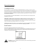
Electrical information Grounding Instructions IN THE EVENT OF A MALFUNCTION OR BREAKDOWN, grounding provides the path of least resistance for electric current and reduces the risk of electric shock. This tool is equipped with an electric cord that has an equipment grounding conductor and a grounding plug. The plug MUST be plugged into a matching outlet that is properly installed and grounded in accordance with ALL local codes and ordinances. DO NOT MODIFY THE PLUG PROVIDED.
Electrical information (continued) Guidelines for using extension cords WARNING: This tool is for indoor use only. Do not expose to rain or use in damp locations. Make sure your extension cord is in good condition. When using an extension cord, be sure to use one heavy enough to carry the current your product will draw. An undersized cord will cause a drop in line voltage resulting in loss of power and overheating.
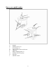
Know your spindle sander A B C D E F G H I Spindle Sanding sleeves (6) Throat plates (6) Upper spindle washer and hex nut Table top Rubber sanding drums (5) Sanding drum storage peg Dust port ON/OFF switch 8
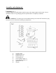
Assembly and adjustments Unpacking (Fig. 1) Carefully unpack the spindle sander and all its parts, and compare against the list below. Do not discard the carton or any packaging until the spindle sander is completely assembled. WARNING: To avoid injury from accidental starting, turn switch OFF and remove plug from power source outlet before making any adjustments.
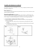
Assembly and adjustments (continued) This spindle sander requires some assembly. For your safety, completely assemble the spindle sander prior to plugging it in. Dust collection (Fig. 2) A 2-1/2" dust port is located at the back of the spindle sander. This port can be connected to a dustcollection system (not provided). Mount the spindle sander (Fig. 3 and 4) To mount the spindle sander in a permanent location, secure the base to a solid benchtop.
Assembly and adjustments (continued) Sanding sleeve selection Select and install a sanding sleeve that is close in size to the workpiece that you will be sanding, and then select the matching throat plate. Throat plate selection (Fig. 5) WARNING: Failure to use the correct throat plate with its matching sanding sleeve could result in pinched fingers or the workpiece being pulled down between the throat plate and the sanding sleeve.
Assembly and adjustments (continued) Install a sanding sleeve (Fig. 6 and 7) All of the sanding sleeves, except the smallest 1/2" sleeve, fit over a similar sized rubber sanding drum. 1. Place the lower spindle washer (2) over the spindle (1) with the fin side facing down. 2. Select a sanding sleeve (5) for the job that you are planning. Select the corresponding rubber sanding drum (4). Note: Do not use a sanding drum with the 1/2" sanding sleeve. 3.
Operation ON/OFF switch (Fig. 8) 1. To turn the sander ON, insert the safety key (1) in the switch (2), and then move the switch upward to the ON position. 2. To turn the sander OFF, move the switch (2) 1 downward to the OFF position. 3. To lock the switch in the OFF position, pull the safety key (1) out of the switch (2). The switch will not operate with the safety key removed.
Maintenance WARNING: Turn the switch to the OFF position and unplug the power cord from the electric outlet before adjusting or performing maintenance on the spindle sander. Lubrication Ball bearings are grease packed at the factory, and require no further lubrication. Use a spray lubricant on all moving table parts to ensure smooth operation. General Maintenance Before each use, check for damaged, missing, or worn parts.
Troubleshooting 1. Over time, if the performance of the tool diminishes, or it stops working completely, it may be necessary to replace the Carbon Brushes (34) by removing the Brush Holder (33). This procedure should be completed by a qualified technician. If the Carbon Brushes are not worn down, try cleaning the Carbon Brush tips with an ink eraser. 2. If the Sanding sleeve stops rotating when you touch it or press the stock material against it, turn off the machine at once.
Exploded view and parts list 16
Exploded view and parts list (continued) 17
Exploded view and parts list (continued) Part# 1 2 3 4 5 6 7 8 9 10 11 12 13 14 15 16 17 18 19 20 21 22 23 24 25 26 27 28 29 30 31 32 33 34 35 36 37 38 39 40 41 Stock # Description Part# 90225‐001 90225‐002 90225‐003 90225‐004 90225‐005 90225‐006 90225‐007 90225‐008 90225‐009 90225‐010 90225‐011 90225‐012 90225‐013 90225‐014 90225‐015 90225‐016 90225‐017 90225‐018 90225‐019 90225‐020 90225‐021 90225‐022 90225‐023 90225‐024 90225‐025 90225‐026 90225‐027 90225‐028 90225‐029 90225‐030 90225‐031 90225‐032 9
Exploded view and parts list (continued) Part# 84 85 86 87 88 89 90 91 92 93 94 95 96 97 98 99 Stock # 90225‐084 90225‐085 90225‐086 90225‐087 90225‐088 90225‐089 90225‐090 90225‐091 90225‐092 90225‐093 90225‐094 90225‐095 90225‐096 90225‐097 90225‐098 90225‐099 Description Part# Warning label(Ⅰ) 100 Cord clamp 101 Screw 4.2x15 102 Thread 103 Screw 4.2x10 104 Rubber foot 105 Washer 6 106 Spring washer 6 107 Screw 6x16 108 Bottom plate 109 Screw 4.
Warranty WEN Products is committed to build tools that are dependable for years. Our warranties are consistent with this commitment and our dedication to quality. LIMITED WARRANTY OF WEN CONSUMER POWER TOOLS PRODUCTS FOR HOME USE GREAT LAKES TECHNOLOGIES, LLC ("Seller") warrants to the original purchaser only, that all WEN consumer power tools will be free from defects in material or workmanship for a period of two (2) years from date of purchase.