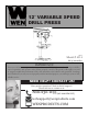
2˝ VARIABLE SPEED DRILL PRESS 2015 Model # 4214 bit.ly/wenvideo IMPORTANT: Your new tool has been engineered and manufactured to WEN’s highest standards for dependability, ease of operation, and operator safety. When properly cared for, this product will supply you years of rugged, trouble-free performance. Pay close attention to the rules for safe operation, warnings, and cautions. If you use your tool properly and for intended purpose, you will enjoy years of safe, reliable service.
TABLE OF CONTENTS 2 3 4 5 7 8 16 19 20 21 24 Technical Data General Safety Rules Specific Safety Rules For Drill Press Electrical Information Know Your Drill Press Assembly and Adjustments Operation Maintenance Troubleshooting Exploded View and Parts List Warranty TECHNICAL DATA Model Number: Motor: Speed: Chuck Capacity: Stroke: Capacity: Table tilt: Laser: Weight: 2 4214 120 V, 60 Hz, 5 A 580-3200 RPM (no load) 1/8--5/8˝ 3-1/8˝ 6˝ (chuck to column) 20˝ (chuck to base) 0 to 45° left and right Class III
GENERAL SAFETY RULES Safety is a combination of common sense, staying alert and knowing how your item works. SAVE THESE SAFETY INSTRUCTIONS. WARNING: To avoid mistakes and serious injury, do not plug in your tool until the following steps have been read and understood. 1. READ and become familiar with this entire instruction manual. LEARN the tool’s applications, limitations, and possible hazards. 2. AVOID DANGEROUS CONDITIONS. Do not use power tools in wet/damp areas or expose them to rain.
GENERAL SAFETY RULES 14. NEVER STAND ON A TOOL. Serious injury could result if the tool tips or is accidentally hit. DO NOT store anything above or near the tool. 15. DO NOT OVERREACH. Keep proper footing and balance at all times. Wear oil-resistant rubber-soled footwear. Keep the floor clear of oil, scrap, and other debris. 16. MAINTAIN TOOLS PROPERLY. ALWAYS keep tools clean and in good working order. Follow instructions for lubricating and changing accessories. 17. CHECK FOR DAMAGED PARTS.
SPECIFIC RULES FOR DRILL PRESS 10. Always stop the drill before removing scrap pieces from the table. 11. Use clamps or a vise to secure a workpiece to the table. This will prevent the workpiece from rotating with the drill bit. 12. Do not wear gloves when operating a drill press. 13. Set the drill press to the speed that is appropriate for the material being drilled. 14.
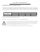
ELECTRICAL INFORMATION GUIDELINES FOR USING EXTENSION CORDS Make sure your extension cord is in good condition. When using an extension cord, be sure to use one heavy enough to carry the current your product will draw. An undersized cord will cause a drop in line voltage resulting in loss of power and overheating. The table below shows the correct size to be used according to cord length and nameplate ampere rating. When in doubt, use a heavier cord. The smaller the gauge number, the heavier the cord.
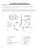
KNOW YOUR DRILL PRESS Fig.
ASSEMBLY AND ADJUSTMENTS UNPACKING (Fig. 2) Unpack the drill press and all of its parts. Compare against the list below. Do not discard the carton or any packaging until the drill press is completely assembled. To protect the drill press from moisture, a protective coating has been applied to the machine’s surfaces. Remove this coating with a soft cloth moistened with kerosene or WD-40®. Do not use acetone, gasoline, or lacquer thinner to clean. Apply a coat of good paste wax to the table and column.
ASSEMBLY AND ADJUSTMENTS WARNING: If any part is missing or damaged, do not plug the drill press in until the missing or damaged part is repaired or replaced. The column assembly (column, column support, rack, rack collar, and table support bracket) must be attached to the base. The table and table support handles must be attached to the table support bracket. The motor housing must be attached to the column.
ASSEMBLY AND ADJUSTMENTS DRILL PRESS HEAD TO COLUMN (Fig. 5) CAUTION: The drill press head is heavy. To avoid injury, two people should lift it into position. 1. Carefully lift the drill press head assembly (1) and position it over the column (2). 2. Place the mounting opening (3) on the drill press head over the top of the column. Make sure the drill press head is seated properly on the column. Fig. 5 3. Align the direction of the drill press head with the direction of the base and the table. 4.
ASSEMBLY AND ADJUSTMENTS MOUNT THE DRILL PRESS (Fig. 8) The drill press must be securely fastened through the mounting holes to a stand or workbench with heavy-duty fasteners. This will prevent the drill press from tipping over, sliding, or walking during operation. IMPORTANT: If the stand or workbench has a tendency to move during operation, fasten the workbench securely to the floor. LED BULB An LED bulb has been assembled in the socket of the head. Fig.
ASSEMBLY AND ADJUSTMENTS RAISE OR LOWER THE TABLE (Fig. 11) 1. Loosen the support lock handle (1) and turn the crank handle (2) until the table is at the desired height. 2. Tighten the support lock handle before drilling. ROTATE THE TABLE (Fig. 11) 1. Loosen the support lock handle (1) and turn the table around the column to the desired position. Note: The rack should rotate around the column with the table support bracket.
ASSEMBLY AND ADJUSTMENTS WARNING: To avoid injury, make sure the chuck key is removed from the chuck before starting any drilling operation. INSTALLING A DRILL BIT (Fig. 13) 1. Place the chuck key (1) into the side keyhole of the chuck (2), meshing the key with the gear teeth. 2. Turn the chuck key counterclockwise to open the chuck jaws (3). 3. Insert a drill bit (4) into the chuck far enough to obtain the maximum grip of the chuck jaws. 4.
ASSEMBLY AND ADJUSTMENTS ADJUSTING THE LASER (Fig. 15 and 16) WARNING: Do not stare directly at the laser beam. Please observe all safety rules. • Never aim the beam at a person or an object other than the workpiece. • Do not project the laser beam into the eyes of others. • Always make sure the laser beam is aimed at a workpiece that does not possess reflective surfaces, as the laser beam could project into your eyes or the eyes of others. 1. Place a workpiece on the table. 2.
ASSEMBLY AND ADJUSTMENTS ANGULAR “PLAY” OF THE SPINDLE (Fig. 18) Move the spindle to the lowest downward position and hold in place. Try to make the spindle revolve around its axis while also moving it with a side motion. If there is too much “play”, proceed as follows: 1. Loosen the lock nut (1). 2. Without obstructing the upward and downward motion of the spindle, turn the screw (2) clockwise to eliminate the “play.” Note: A little bit of “play” is normal. Fig. 18 3. Tighten the lock nut (1).
OPERATION DRILL PRESS ON/OFF SWITCH (Fig. 20) 1. To turn the drill press ON, insert the yellow safety key (1) into the switch housing (2). As a safety feature, the switch cannot be turned ON without the safety key. 2. Flip the switch upward to the ON position. 3. To turn the drill press OFF, flip the switch downward. 4. To lock the switch in the OFF position, remove the safety key (1) from the switch. Store the safety key in a safe place. LIGHT AND LASER LINE ON/OFF SWITCHES (Fig.
OPERATION ADJUST THE DRILLING DEPTH (Fig. 22) The depth gauge controls the maximum distance the drill bit will move up or down. To stop the drill bit at a pre-measured depth, loosen the depth scale knob (1) by push button (2) until the bottom of the knob is aligned with the desired depth mark (3) on the gauge scale. Drilling an unmeasured blind hole (not all the way through the workpiece) to a given depth can be done using either the depth scale method or the workpiece method. DEPTH SCALE METHOD (Fig.
OPERATION DRILLING SPEEDS There are a few important factors to keep in mind when determining the best drilling speed: • Material type • Hole size • Drill bit or cutter type • Quality desired Smaller drill bits require greater speed than larger drill bits. Softer materials require greater speed than harder materials. See page 19 for recommended speeds for particular materials. DRILLING METAL • Use metal-piercing twist drill bits.
OPERATION Recommended speed for drill bit size and materials MAINTENANCE WARNING: For your safety, turn the switch off and remove the plug from the power supply before maintaining or lubricating the drill press. Vacuum sawdust or metal shavings that accumulate in and on the motor, pulley housing, table, and work surface. Apply a light coat of paste wax to the column and table to help keep these surfaces clean and rust-free.
TROUBLESHOOTING PROBLEM Noisy operation SOLUTIONS 1) Adjust the belt tension (See REPLACE THE BELT section) 2) Lubricate the spindle 3) Tighten the retaining nut on the pulley insert 4) Tighten the set screw on the side of the motor pulley The drill bit burns or 1) Drilling at the incorrect speed 1) Change the speed smokes 2) The wood chips are not coming out 2) Retract the drill bit frequently to clear the of the hole chips 3) Dull drill bit 3) Resharpen or replace the drill bit 4) Feeding the workpiece t
EXPLODED VIEW & PARTS LIST 21
EXPLODED VIEW & PARTS LIST Item # 1 2 3 4 5 6 7 8 9 10 11 12 13 14 15 16 17 18 19 20 21 22 23 24 25 26 27 28 29 30 31 32 33 34 35 36 37 38 39 40 41 42 43 22 Stock # 4214B-001 4214B-002 4214B-003 4214B-004 4214B-005 4214B-006 4214B-007 4214B-008 4214B-009 4214B-010 4214B-011 4214B-012 4214B-013 4214B-014 4214B-015 4214B-016 4214B-017 4214B-018 4214B-019 4214B-020 4214B-021 4214B-022 4214B-023 4214B-024 4214B-025 4214B-026 4214B-027 4214B-028 4214B-029 4214B-030 4214B-031 4214B-032 4214B-033 4214B-034 4214B
EXPLODED VIEW & PARTS LIST Item # 89 90 91 92 93 94 95 96 97 98 99 100 101 102 103 104 105 106 107 108 109 110 111 112 Stock # 4214B-089 4214B-090 4214B-091 4214B-092 4214B-093 4214B-094 4214B-095 4214B-096 4214B-097 4214B-098 4214B-099 4214B-100 4214B-101 4214B-102 4214B-103 4214B-104 4214B-105 4214B-106 4214B-107 4214B-108 4214B-109 4214B-110 4214B-111 4214B-112 Description Rack shaft Big washer 8 Bolt M8x12 Screw M3x10 Lamp socket bracket Lamp socket LED light Screw M4x8 Indicator Rack collar Screw M6x
LIMITED TWO YEAR WARRANTY WEN Products is committed to building tools that are dependable for years. Our warranties are consistent with this commitment and our dedication to quality. LIMITED WARRANTY OF WEN CONSUMER POWER TOOLS PRODUCTS FOR HOME USE GREAT LAKES TECHNOLOGIES, LLC (“Seller”) warrants to the original purchaser only, that all WEN consumer power tools will be free from defects in material or workmanship for a period of two (2) years from date of purchase.