
User Manual


13
Fig. I
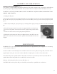
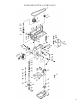
SPINDLE RETURN SPRING (Fig. J)
The spindle is equipped with an auto-return mechanism. The main components are a spring and a notched hous-
ing. The spring was properly adjusted at the factory and should not be readjusted unless absolutely necessary.
WARNING: ALWAYS WEAR WORK GLOVES TO PREVENT INJURY DURING SPINDLE RETURN
SPRING ADJUSTMENTS.
1. Unplug the drill press.
2. Loosen the two housing nuts (2) approximately 1/4” (6 mm). Do not remove the nuts from the threaded shaft.
Do not allow the spring or spring housing to slip out of control. Keep a firm grip on the return spring using work
gloves.
3. While firmly holding the spring housing (3), carefully pull the spring housing out until it clears the raised notch
(2).
4. Turn the housing so that the next notch is engaged with the raised notch (2).
• To increase the spindle return tension, turn the spring housing counter-clock-
wise.
• To decrease the tension, turn the spring housing clockwise.
5. Tighten the two housing nuts. Do not overtighten the two nuts. If the nuts are
tightened too much, the movement of the spindle and feed handles will become
sluggish.
Fig. J
1
2
3
ASSEMBLY AND ADJUSTMENTS
WARNING: For your safety, turn the switch off and remove the plug from the power supply before maintaining
or lubricating the drill press.
Vacuum sawdust or metal shavings that accumulate in and on the motor, pulley housing, table, and work surface.
Apply a light coat of paste wax to the column and table to help keep these surfaces clean and rust-free.
The ball bearings in the spindle and the V-belt pulley assembly are greased and permanently sealed. Pull the
spindle down and oil the spindle sleeve moderately every three months.
Lubricate the locking knobs if they become difficult to use.
CAUTION: All servicing of the drill press should be performed by a qualified service technician.
MAINTENANCE