
Use and Care Manual


9
ASSEMBLY AND ADJUSTMENTS
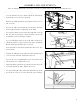
ALIGN THE BEVEL INDICATOR (Fig. 3-6)
The bevel indicator has been factory adjusted. It should be
rechecked prior to use for best operation.
1. Remove the blade guard foot (1) using the hex key to loos-
en the screw (2).
2. Loosen the table bevel lock knob (3) and move the table
until it is approximately at a right angle to the blade.
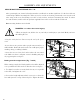
3. Loosen the locking nut (5) on the table adjusting screw (6)
under the table by turning it counter-clockwise. Lower the
table adjusting screw by turning it clockwise.
4. Use a combination square (7) to set the table exactly 90° to
the blade (8). If there is space between the square and blade,
adjust the table angle until the space is closed.
5. Lock the table bevel lock knob under the table (3) to pre-
vent movement.
6. Tighten the adjusting screw under the table until the tip of
the screw touches the table. Tighten the lock nut.
7. Loosen the screw (4) holding the bevel scale pointer and
position pointer to 0°. Tighten the screw.
8. Attach the blade guard foot (1) using the hex key (2) so the
foot rests flat against the table. Tighten the screw.
Note: Avoid setting the edge of the table against the top of the
motor. This can cause excess noise when the saw is running.
Fig. 5
Fig. 6
5
6
3
4
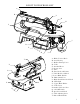
Prior to making adjustments, mount the scroll saw on a stable surface. See “Bench mounting the saw.”
Fig. 4
Fig. 3
1
2