
Use and Care Manual


9
OPERATION
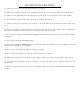
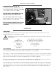
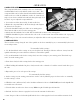
MOUNTING THE LATHE (FIG. B)
The lathe should be mounted on a strong, heavy
workbench. Take the necessary precautions when
moving the lathe. Assistance may be required.
Bolt the machine firmly to the workbench us-
ing the tapped holes. To do this remove the M6
screws securing the rubber feet in place. Drill four
M6 clearance holes in the worktop and find wash-
ers and M6 screws long enough to securely hold
the unit in place.
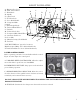
HEADSTOCK
The headstock contains the motor, pulleys and the drive belt that turn the spindle used to create your workpiece.
The spindle has a MT3 taper for use in conjunction with a face plate or turning clamp. The spindle has a flange
attached with 6 holes arranged to mount different fixtures, such as chuck jaws and face plates. The speed of the
spindle is adjusted via the Variable Speed Controller on the control panel. The speed ranges can be swapped
between two ranges with the lever on the back of the headstock. Do not change the speed range during operation.
CARRIAGE
The carriage is the portion of the lathe that moves the Cross Slide and Compound Slide across the bed. It can be
manually fed, or driven with the lead screw by using a drive nut with the lead screw Direction Lever.
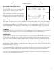
CROSS SLIDE
The cross slide is used to move the tool post and cutting tool across the bed, perpendicular to the lead screw and
the center axis of the spindle. The cross slide is adjusted via a handwheel with precision tick marks, each indi-
cating 0.001”. This scale will rotate with the handwheel when it is turned to feed the cross slide back and forth.
Before beginning a turning, perform the following steps to adjust and zero your cross slide:
1. Turn the handwheel counterclockwise to back the cross slide 0.015” away from your starting point, then slowly
turn the handle clockwise until the cross slide returns to the starting position. This removes any play in the slide to
help make the scale more accurate.
2. Now hold the handwheel steady and with your other hand rotate the scale so the “0” lines up with the “0.000”
mark on the cross slide. From this point the slide will remain accurate as long as you only move it forward.
3. Any time you back feed the slide away from your workpiece you will have to repeat steps 1 and 2 before mov-
ing the cross slide forward again for the next cut.
Fig. B