
Use and Care Manual
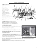
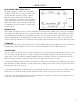

A - Running Gear Cover
B - Lathe Control Panel
C - Head Stock
D - Spindle
E - 3-Jaw Chuck
F - Tool Post Lock
G - Cross Slide Handle
H - Compound Slide
I - Quill
J - Tailstock Quill Lock
K - Tailstock Hand Wheel
L - Tailstock
M - Tailstock Lock Nut
N - Compound Slide Hand Wheel
O - Automatic Feed Lever
P - Cross Slide
Q - Manual (Carriage) Feed Handle
R - Tool Post
NOT PICTURED (ref. page 8 for locations):
High/Low Speed Range Lever (behind headstock)
Forward/Neutral/Reverse Lever (behind headstock)
7
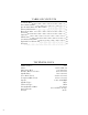
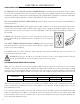
AMPERAGE
REQUIRED GAUGE FOR EXTENSION CORDS
25 ft. 50 ft. 100 ft. 150 ft.
4A 18 gauge 16 gauge 16 gauge 14 gauge
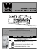
KNOW YOUR LATHE
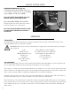
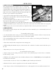
LATHE CONTROL PANEL
Before operating your lathe, become familiar with the controls.
Figure A below depicts the control panel.
A. VARIABLE SPEED CONTROLLER: Allows the adjust-
ment of the lathe’s speed from 0 to 2500 RPM.
B. EMERGENCY SHUTOFF: Stops power to the unit when
pressed during operation.
C. SPINDLE DIRECTION SELECTOR: Allows the user to
select the direction of the spindle between clockwise (forward),
neutral (O), and counterclockwise (reverse).
D
Fig. A - Lathe Control
E
H
F
G
A
Q
N
I
L
O
P
R
C
J
K
M
B
DO NOT CHANGE THE SPINDLE DIRECTION WHILE THE UNIT IS RUNNING! IT WILL
DAMAGE THE LATHE!
D. FUSE CAP: Contains the fuse that protects the unit from circuit overloads.