
Use and Care Manual


GEAR TRAIN
WARNING: Before making any of these adjustments, turn off and unplug the lathe from its power source.
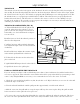
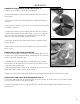
The gear train is located on the headstock opposite the spindle. The drive gear is located under a cover secured
by two hex screws. The gear train is used to drive the lead screw that allows the Auto Feed Function to operate.
As the gear train turns, it turns the Lead screw which moves the saddle across the bed of the lathe. The direction
13
OPERATION
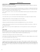
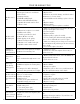
THREADS PER INCH (TPI)
TPI
Gear Size (mm)
A B C D
12 40 65 / 30
13 40 65 60 30
14 40 65 / 35
16 40 65 / 40
18 40 65 / 45
19 40 50 60 57
20 40 65 / 50
22 40 65 / 55
24 40 65 / 60
26 40 60 / 65
28 20 65 / 35
32 20 65 / 40
36 20 65 / 45
38 20 50 60 57
40 20 65 / 50
44 20 65 / 55
48 20 65 / 60
52 20 60 / 65
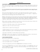
METRIC THREAD PITCH
CHART
mm /
pitch
Gear Size (mm)
A B C D
0.4 20 50 40 60
0.5 20 50 / 60
0.6 40 50 30 60
0.7 40 50 35 60
0.8 40 50 40 60
1.0 20 60 / 30
1.25 50 40 / 60
1.5 40 60 / 40
1.75 35 60 / 30
2.0 40 60 / 30
is set using the Lead screw Direction Lever. Adjusting it to forward will
send the saddle towards the headstock. Reverse sends it away, and neu-
tral disengages the lead screw so the saddle can be manually fed.
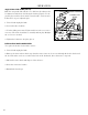
The feed rate of the lead screw can be set by changing the gears in the
gear train (Fig. E). Switching the diameter of the gears and the order
of the gears will change the torque and speed of lead screw, allowing
for different threads to be turned with the lathe. The Threading Chart
to the right shows the gear arrangements to use to achieve different
threads per inch (TPI) or metric pitches when using the lead screw.
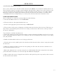
To change the gears to match up with these gear charts follow these
steps:
1. Remove the gear cover to expose the drive gear.
2. Loosen the adjustment nut at the bottom of the gear train to dis-
engage the gears from one another. Remove the necessary gears and
replace them with the appropriate gears. That is, the gears that have the
proper number of teeth in the positions called for (30, 40, 60, and 65
teeth). Note that sometime configurations do not require gears in every
position, and some require you to move the bushings from one shaft to
another for gears to properly fit in place.
3. Position the gears so their teeth will mesh together properly once the
adjuster is tightened.
ADJUSTER
A
B
C
D
Fig. E