
Product Manual

8
TO ASSEMBLE
NOTE: Before assembling, carefully wipe off all grease and rust-protectant coating with a soft cloth. Use kerosene
to fully remove the grease and coating. Apply a light coat of good-quality paste wax to prevent rusting and ensure
ease of movement between parts.
Attach the plastic handles to the rims of the manual feed and tailstock feed handles respectively. Ensure the nuts
are tight and the handles spin freely about the bolts without excessive end play.
The carriage, cross-slide and compound slide adjustments are all factory set to ensure smooth movement in both
directions. However the adjustments may have been misaligned during transportation. This will be indicated by
stiff or erratic movement. Refer to “Settings and Adjustments” for adjustment methods.
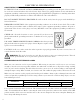
All hex keys and wrenches necessary to carry out various adjustments are supplied together with a chuck key for
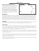
the 3-jaw chuck. The fuse socket (Fig. A) is located on the main control panel.
The four M6 pan-head screws are used to attach the chip tray and rubber feet to the tapped holes in the under-
side of the lathe body. Insert the screws through the feet, through the chip tray, and tighten in the threaded holes.
We strongly recommend that to provide maximum stability and safety, users should secure the lathe to a firm
foundation as described under “Mounting the Lathe” below.
UNPACKING
Carefully unpack the lathe and all its parts. Compare against the list below. Do not discard the carton or any
packaging until the lathe is completely assembled.
Lathe
Rubber Feet (4)
M6 Pan Head Screws (4)
Hex Keys (4)
Chuck Key
Plastic Oil Container (Oil not included)
Spare Fuse
Plastic Handles w/ Nuts and Bolts
No. 2 Morse Taper Center (Tailstock)
External Jaws for 3-Jaw Chuck (3)
8 x 10 mm Wrench
14 x 17 mm Wrench
Gear Set
Face Shield
A
B
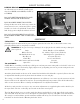
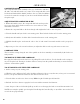
BEHIND HEADSTOCK (FIG. B)
A) : Allows the user to shift the spindle speed
range from HIGH (0-2500 RPM) to LOW (0-
1100 RPM).
DO NOT SHIFT FROM HIGH TO LOW
WHILE THE LATHE IS RUNNING!
B) LEAD SCREW DIRECTION LEVER:
Change the direction of the lead screw rotation be-
tween forward, reverse, and neutral. This is spring-
loaded, so it needs to be pulled OUT (away from
lathe body), position adjusted, and then released
DO NOT CHANGE DIRECTION OF THE
LEAD SCREW WHILE THE LATHE IS RUN-
NING!
ASSEMBLY
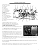
KNOW YOUR LATHE
WARNING: If any part is missing or damaged, do not plug in the tool until the missing or damaged
part is replaced.
Fig. B