
Product Manual
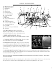
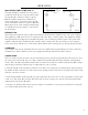

A - Running Gear Cover
B - Lathe Control Panel
C - Head Stock
D - Spindle
E - 3-Jaw Chuck
F - Tool Post Lock
G - Cross Slide Handle
H - Compound Slide
I - Quill
J - Quill Lock
K - Tailstock Hand Wheel
L - Tailstock
M - Tailstock Lock Nut
N - Compound Slide Handle
O - Automatic Feed Lever
P - Cross Slide
Q - Manual (Carriage) Feed Handle
R - Tool Post
NOT PICTURED (See page 8 for locations):
High/Low Speed Range Lever (behind headstock)
Forward/Neutral/Reverse Lever (behind headstock)
7
KNOW YOUR LATHE
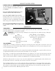
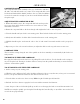
LATHE CONTROL PANEL (FIG. A)
Before operating your lathe, become familiar with the controls.
A. VARIABLE SPEED CONTROLLER: Allows the adjust-
ment of the lathe’s speed from 0 to 2500 RPM.
B. EMERGENCY SHUTOFF: Stops power to the unit when
pressed during operation. Button must be UP (clasp released)
to permit operation. Eye guard must also be DOWN to permit
operation. Raising eye guard before or during operation causes
motor fault.
D
E
H
F
G
A
Q
N
I
L
O
P
R
C
J
K
M
B
C. SPINDLE DIRECTION SELECTOR: Allows the user to select the direction of the spindle between clock-
wise (forward), neutral (O), and counterclockwise (reverse). Forward = toward operator (clockwise when viewed
from the headstock end; opposite for reverse.
DO NOT CHANGE THE SPINDLE DIRECTION WHILE THE UNIT IS RUNNING! IT WILL DAM-
AGE THE LATHE!
D. FUSE CAP: Contains the fuse (4A) that protects the unit from circuit overloads. The fuse can be removed by
turning 1/4-turn counterclockwise with Phillips-head screwdriver, then pulling fuse and cap out.
A
C
B
D
Fig. A