
Product Manual


16
OPERATION
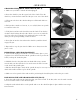
BEVEL CUTTING
In order to perform a bevel cut, it is necessary to use the compound slide as well as the cross slide. To align the
compound slide for a bevel cut, align it to the proper angle following the procedure in the “Compound Slide” sec-
tion on page 10.
Once the compound slide is aligned to the proper angle, follow these steps to create the bevel:
1. Mark your end point of the bevel if necessary using the methods for a normal turning.
2. Set and zero out the cross slide to the proper starting point.
3. Turn the lathe on and set the spindle to the appropriate RPM.
4. Use the handle on the compound slide to feed the cutting tool along the end of the workpiece. This will create
the bevel cut at the angle you set it to.
5. Back off the cutting tool 2 turns and reset the compound slide to the starting point. Feed the cutting tool back
in to the cutting depth.
6. Repeat until your bevel is the desired length and position.
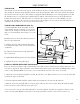
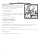
TO CUT THREADS
1. Adjust the compound slide so the tool is at the appropriate angle for the desired
thread.
2. Place the tool tip so that it is vertically centered and perpendicular to the workpiece.
3. Engage the thread dial with the lead screw. The thread dial is located next to the
auto-feed lever on the carriage. There is a socket-head cap screw on the side; loosen
the screw using one of the included hex wrenches and adjust the body of the thread dial
so that its gear meshes with the threads on the lead screw. Tighten the socket head cap
screw, ensuring that the gear stays engaged with the lead screw threads.
4. Use the gear ratio charts to determine the proper gear ratio and install the proper
gears (See “Gear Train” on page 13).
5. Turn the lathe on and set the RPM using the Variable Speed Controller. Make sure
the lead screw is feeding in the proper direction by engaging the feed lever. When you
are sure it is going in the right direction disengage the feed lever and turn off the lathe.
Ensure that the carriage is beyond the end of the workpiece.
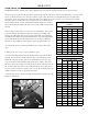
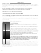
6. Read the settings off the thread dial chart (left) to get the proper setting for the thread
dial. Make sure the thread dial always engages the half nut on the same mark for every
pass of the cutting tool. If you don’t do this you may cut off threads created in your
THREAD DIAL
TPI SCALE
12 1, 3, 5, 7
13 1
14 1 or 5
16 1 - 8
18 1 or 5
19 1
20 1, 3, 5, 7
22 1 or 5
24 1 - 8
26 1 or 5
28 1, 3, 5, 7
32 1 - 8
36 1, 3, 5, 7
38 1 or 5
40 1 - 8
44 1, 3, 5, 7
48 1 - 8
52 1, 3, 5, 7
previous cut. That is, the lever needs to be pushed down at the same point in order to cut threads correctly. If you
engage the lever when the dial is not pointing to an indicator mark, you may stall the lead screw, which will cause
it to drop into Neutral and stop.