
Use and Care Manual

ASSEMBLY & ADJUSTMENTS
A A
B B
C C
D D
E E
F F
8
8
7
7
6
6
5
5
4
4
3
3
2
2
1
1
DRAWN
CHK'D
APPV'D
MFG
Q.A
UNLESS OTHERWISE SPECIFIED:
DIMENSIONS ARE IN MILLIMETERS
SURFACE FINISH:
TOLERANCES:
LINEAR:
ANGULAR:
FINISH:
DEBURR AND
BREAK SHARP
EDGES
NAME
SIGNATURE
DATE
MATERIAL:
DO NOT SCALE DRAWING
REVISION
TITLE:
DWG NO.
SCALE:1:10
SHEET 1 OF 1
A3
WEIGHT:
34034.solidworks
1
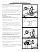
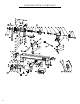
ADJUSTING THE SPEED (Fig. 11 - 14)
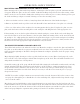
Your variable speed lathe has three speed ranges: Low 250-720
RPM, Medium 600-1700 RPM, and High 1200-3550 RPM. Al-
ways start at slower speeds for rough cuts and larger workpieces.
Use faster speeds for refined cuts and detailed work.
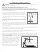
Set the suitable speed range for your operation by adjusting the
belt position. Change the speed within a speed range using the
speed adjustment knob. The speed will be displayed on the
digital RPM readout (Fig. 15 - 1) on the front panel.
1. When changing speed ranges, always make sure to turn off
and disconnect the lathe to prevent accidental injuries.
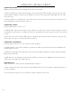
2. Loosen the belt access panel knob (Fig. 11 - 1) on the top
front of the headstock and open the belt drive access panel.
3. Loosen (but do not remove) the four screws holding the lower
belt drive plate (Fig. 12 - 1) onto the left side of the headstock.
Lift and remove the lower belt drive plate.
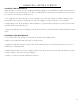
4. Loosen the motor tensioning locking handle (Fig. 13 - 1).
NOTE: The screw at the center of the locking handle can be
loosened to rotate the locking handle to an optimal position.
5. Pull upwards on the tensioning handle (Fig. 13 - 2) to relieve
tension on the belt. It may help to wedge a piece of wood or
other support under the tensioning handle to keep it in place
while you adjust the belt position.
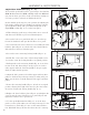
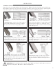
6. Adjust the belt’s position on both the upper and lower drive
pulleys to the desired speed range setting according to Fig. 14.
Make sure the belt is vertically aligned on the upper and lower
pulleys.
7. Lower the tensioning handle (Fig. 13 - 2) back to its original
position, allowing the weight of the motor to place the belt un-
der tension. Tighten the locking handle (Fig. 13 - 1).
8. Replace the lower belt drive plate (Fig. 12 - 1) and tighten the
screws. Lower the upper belt drive access panel (Fig. 11) and
tighten the belt drive access panel knob.
9. Use the speed adjustment knob (Fig. 15 - 3) on the front
panel to set the speed within your selected speed range. Use the
forward/reverse switch (Fig. 15 - 2) to set the rotational direc-
tion. DO NOT change the direction when the tool is running.
2
1
A A
B B
C C
D D
E E
F F
8
8
7
7
6
6
5
5
4
4
3
3
2
2
1
1
DRAWN
CHK'D
APPV'D
MFG
Q.A
UNLESS OTHERWISE SPECIFIED:
DIMENSIONS ARE IN MILLIMETERS
SURFACE FINISH:
TOLERANCES:
LINEAR:
ANGULAR:
FINISH:
DEBURR AND
BREAK SHARP
EDGES
NAME
SIGNATURE
DATE
MATERIAL:
DO NOT SCALE DRAWING
REVISION
TITLE:
DWG NO.
SCALE:1:10
SHEET 1 OF 1
A3
WEIGHT:
34034.solidworks
1
Low
250
Belt Position Speed Chart (RPM)
600
1200
720
1700
3550
Med
High
Fig. 11
Fig. 12
Fig. 13
Fig. 14
Fig. 15
1
2
3
12