AIR COMPRESSOR IDENTIFICATION For information and questions contact customer service at 1-800-232-1195. Please fill out the information below and have it accessible prior to calling. For the Serial Number refer to the specifications sticker on your Air Compressor.
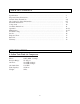
TABLE OF CONTENTS Specifications ………………………………………………………………………….. Important Safety Instructions...………………………………………………………… General Safety Instructions…………………………………………………………….. Air Compressor Safety Information …………………………………………………... Electrical Instructions………………………………………………………………….. Components……………………………………………………………………………. Assembly Instructions…………………………………………………………………. Operation……………………………………………………………………………… Maintenance…………………………………………………………………………….
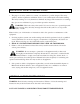
IMPORTANT SAFETY INSTRUCTIONS 1. The purpose of safety symbols is to attract your attention to possible dangers. The safety symbols, and the explanations with them, deserve your careful attention and understanding. The safety warnings do not by themselves eliminate any danger. The instructions or warnings they give are not substitutes for proper accident prevention measures. WARNING: This is the safety alert symbol. It is used to alert you to potential personal injury hazards.
Work Area Safety 1. Keep work area clean and well lit. Cluttered or dark areas invite accidents. 2. Do not operate your Air Compressor in explosive atmospheres, such as in the presence of flammable liquids, gases or dust. Air Compressor motors produce sparks which may ignite the dust or fumes. 3. Keep children and bystanders away from an operating Air Compressor. Electrical Safety 1. Air Compressor plugs must match the outlet. Never modify the plug in any way.
4. Maintain your Air Compressor. Keep your Air Compressor clean for maximum performance. Follow the instructions for lubricating and changing accessories. Keep your Air Compressor dry, clean and free from oil and grease. Check for misalignment or binding of moving parts, breakage of parts and any other condition that may affect your Air Compressor's operation. If damaged, have your Air Compressor repaired professionally before use. Many accidents are caused by a poorly maintained Air Compressor. 5.
15. This product is not a toy. Keep it out of reach from children. 16. People with pacemakers should consult their physician(s) before use. Electromagnetic fields in close proximity to heart pacemaker could cause pacemaker interference or pacemaker failure. WARNING: The brass components of this product contain lead, a chemical known to the State of California to cause birth defects (or other reproductive harm). (California Health & Safety code 25249.5, et seq.) 17.
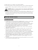
WARNING: This tool/equipment is for indoor use only. Do not expose to rain or use in damp locations. 1. 2. 3. 4. Fig. 1 Tools/equipment with three wire grounding plugs (Fig. 1, A) are intended for use on a circuit that has an outlet that looks like the one illustrated (Fig. 1, B). A temporary adapter (Fig. 1, B & C) may be used to connect this plug to a 2-pole receptacle (Fig. 1, B) if a properly grounded outlet is not available.
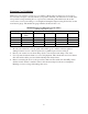
Extension Cord Guidelines Make sure your extension cord is in good condition. When using an extension cord, be sure to use one heavy enough to carry the current your product will draw. An undersized cord will cause a drop in line voltage resulting in loss of power and overheating. The table below shows the correct size to be used according to cord length and nameplate ampere rating. If in doubt, use the next heavier gauge. The smaller the gauge number, the heavier the cord.
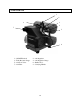
COMPONENTS 1 2 8 3 4 7 5 6 1 – ON/OFF Switch 3 – Tank Pressure Gauge 5 – Air Flow Valve 7 – Air Filter 2 – Air Regulator 4 – Air Regulator Gauge 6 – Rubber Foot 8 – Carrying Handle 10
ASSEMBLY INSTRUCTIONS Unpacking 1. When unpacking, make sure that the machine is intact and undamaged. 2. Please check that the following items are included with your Air Compressor. – Oil Bottle – Air Filter – Oil Breather Cap 3. If any parts are missing or broken, please call our customer services at 1-800-232-1195. 4. Your Air Compressor requires minimum assembly. Remove the parts from the carton. Air Filter Installation (Fig. 3) This Air Compressor is shipped with a plastic plug in the air filter hole.
OPERATION BEFORE OPERATING YOUR NEW AIR COMPRESSOR complete the following steps. 1. Check that all nuts and bolts are secure. 2. Make sure the oil has been properly added to your Air Compressor. 3. Place your Air Compressor on a firm, level surface in a clean, dry, well ventilated area. 4. Your Air Compressor should be located 12 to 18 inches from walls or any other obstruction which would interfere with airflow. Your Air Compressor should be located in a temperature controlled area between 32°F and 95°F.
General Overview 1. To compress air, the piston moves up and down in the cylinder. On the down stroke air is drawn in through the valve inlet. The discharge valve remains closed. On the upstroke of the piston air is compressed. 2. The inlet valve closes and air is forced out through the discharge valve, through the Check Valve, and into the Air Tank. 3. Working air is not available until the compressor has raised the tank pressure above that required at the air service connection. 4.
Monthly Inspect the air system for leaks by applying soapy water to all joints. Tighten these joints if leaks are discovered. 6 Months (or after 250 hours of operation - whichever comes first) Change Air Compressor Oil. Note: Change the oil more often if your Air Compressor is used near paint spraying operations or in dusty environments. Checking the Air Compressor Oil 1. Place your Air Compressor on a level surface. The oil level should be at the red dot on the Oil Sight Glass. 2.
10. Avoid using solvents when cleaning plastic parts, most plastics are susceptible to damage from the various types of commercial solvents. TROUBLESHOOTING Problem Air compressor will not start. Low pressure Safety valve releasing. Oil discharge in air compressor. Cause Thermal overload. Blown fuse or circuit breaker tripped. Loose electrical connections. Restricted air filter. Defective check valve. Air leak in safety valve. Defective pressure switch. Too much oil in crankcase.
SERVICE 1. Mechanical and/or electrical tool/equipment service is to be performed only by professional qualified repair personnel. Service performed by unqualified personnel may result in a risk of injury. 2. When servicing a tool/equipment, use only identical replacement parts. Use of unauthorized parts or failure to follow maintenance instructions may create a risk of electrical shock or injury.
EXPLODED VIEW 17
PARTS LIST Part # 1 2 3 4 5 6 7 8 9 10 11 12 13 14 15 16 17 18 19 20 21 22 23 24 25 26 27 28 29 30 31 32 33 34 35 Stock # 22040-001 22040-002 22040-003 22040-004 22040-005 22040-006 22040-007 22040-008 22040-009 22040-010 22040-011 22040-012 22040-013 22040-014 22040-015 22040-016 22040-017 22040-018 22040-019 22040-020 22040-021 22040-022 22040-023 22040-024 22040-025 22040-026 22040-027 22040-028 22040-029 22040-030 22040-031 22040-032 22040-033 22040-034 22040-035 Description Crankcase Crank Shaft Gask
ONE (1) YEAR LIMITED WARRANTY Remember to save your receipt and to accurately fill out and mail your product registration card. You must provide proof of purchase for all warranty work. POWER PRO products are warranted to be free from defects in materials and workmanship for a period of one (1) year from date of original purchase. Products used for Commercial or Rental use have a warranty period of 90 days from date of original purchase.