502 WELLS BLOOMFIELD, LLC 10 Sunnen Dr., St. Louis, MO 63143 telephone: 314-678-6314 fax: 314-781-2714 www.wells-mfg.
LIMITED WARRANTY STATEMENT Unless otherwise specified, all commercial cooking equipment manufactured by WELLS BLOOMFIELD, LLC is warranted against defects in materials and workmanship for a period of one year from the date of original installation or 18 months from the date of shipment from our factory, whichever comes first, and is for the benefit of the original purchaser only.
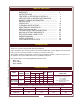
TABLE OF CONTENTS WARRANTY ................................................................ SPECIFICATIONS ....................................................... FEATURES & OPERATING CONTROLS ................... PRECAUTIONS & GENERAL INFORMATION ........... AGENCY LISTING INFORMATION ............................ INSTALLATION ........................................................... OPERATION ................................................................ CLEANING INSTRUCTIONS ...........................
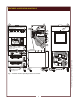
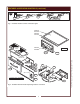
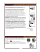
FEATURES & OPERATING CONTROLS 28 28 VENTILATOR CONTROL PANEL see pages 4 & 5 a15 28 1 56 53 19 16 18 a11 18 16 23 23 GRIDDLE CONTROL PANEL see pages 4 & 5 22 a10 ANS UL 40 12 IN CASE OF FIRE ® 41 PULL HANDLE TO ACTIVATE FIRE SUPPRESSION SYST EM 44 a6 43 WARMER CONTROLS see pages 4 & 5 8 9 Fig.
FEATURES & OPERATING CONTROLS (continued) VENTILATOR SECTION ITEM DESCRIPTION COMMENT 1. NAMEPLATE Lists Manufacturer, Model and Serial Number information. Also lists electrical specifications. a6. FIRE SUPPRESSION AGENT TANK (1.5 gal.) Container for Ansulex™ Low-pH liquid fire suppression liquid. 8. ADJUSTABLE (FRONT) LEG Allows the unit to be leveled. 9. RIGID (REAR) CASTER Allows the unit to be easily positioned by lifting the front of the unit slightly. a10.
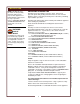
FEATURES & OPERATING CONTROLS (continued) VENTILATOR POWER ON REPLACE PREFILTER CHECK FILTERS V.02 V.03 SERVICE REQUIRED REPLACE FILTER PACK V.04 V.05 V.01 V.06 VCS 2000 VENTLESS COOKING SYSTEM Fig. 2 Ventilator Section Controls & Indicator Lights GRIDDLE SURFACE GREASE TROUGH HUMITROL RACK GREASE DRAWER GRIDDLE G.02 G.01 DRAWER INSERT PAN W.03 W.05 W.06 W.02 W.04 W.01 RWT-STYLE W.08 OPTIONAL ROLL WARMER W.06 W.09 W.07 Fig.
FEATURES & OPERATING CONTROLS (continued) ITEM DESCRIPTION COMMENT VENTILATOR SECTION CONTROLS V.01 POWER SWITCH Energizes blower motor. If, after 10 seconds, proper conditions are met, appliance is energized. V.02 POWER ON INDICATOR GREEN. Glows when POWER switch is ON. V.03 CHECK FILTERS ALARM INDICATOR AMBER. Glows if one or more filters are out of position. Check all filters and baffles for proper installation. V.04* REPLACE PREFILTER ALARM INDICATOR AMBER.
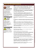
PRECAUTIONS AND GENERAL INFORMATION WARNING: ELECTRIC SHOCK HAZARD All servicing requiring access to non-insulated electrical components must be performed by a factory authorized technician. DO NOT open any access panel which requires the use of tools. Failure to follow this warning can result in severe electrical shock. CAUTION: RISK OF DAMAGE DO NOT connect or energize this appliance until all installation instructions are read and followed.
PRECAUTIONS AND GENERAL INFORMATION (continued) OPERATIONAL NOTES: REPLACE PREFILTER and REPLACE FILTER PACK indicator lights provide a timely warning that a system shut-down is imminent. The actual time between the indicator light coming on and the loss of cooking appliance power will depend upon the cooking conditions. Anytime a dirty PRE-FILTER is replaced, the system airflow will increase. If the condition of the FILTER PACK is marginal, the REPLACE FILTER PACK light could then come on.
INSTALLATION NOTE: DO NOT discard the carton or other packing materials until you have inspected the appliance for hidden damage and tested it for proper operation. Refer to SHIPPING DAMAGE CLAIM PROCEDURE on the inside front cover of this manual. WARNING: RISK OF INJURY Installation procedures must be performed by a qualified technician with full knowledge of all applicable electrical codes. Failure can result in personal injury and property damage.
INSTALLATION (continued) SERVICE TECHNICIAN INSTALLATION NOTES An Ansul® technician must charge and arm the fire suppression system before the ventilator blower will operate. See page 10. Installation and start up must be performed by an Authorized Installation Company. Installer must complete the WARRANTY REGISTRATION form, and record appliance installation particulars on the CUSTOMER SERVICE DATA form in this manual. Certain codes require cooking equipment to be restrained with a RESTRAINT DEVICE.
INSTALLATION (continued) DANGER FIRE HAZARD FIRE SUPPRESSION SYSTEM INSTALLATION 1. Any REMOTE MANUAL PULL STATION must be installed by an authorized ANSUL® distributor in accordance with the AUTHORITY HAVING JURISDICTION. NOTE: If a REMOTE MANUAL PULL STATION is installed, moving the unit for servicing will cause the Ansul® system to discharge. In this case, the unit must only be installed with four fixed legs (i.e. remove rear casters and replace with legs).
INSTALLATION (continued) FILTERS INSTALLATION 1. FILTER PACK: Ships installed in the hood. If the FILTER PACK is not in position, the CHECK FILTERS indicator will light. If the FILTER PACK becomes clogged, the REPLACE FILTER PACK indicator will glow. To install the FILTER PACK: Position the filter pack with the charcoal portion UP. Slide the filter pack toward the rear of the unit until it contacts the guides on the back panel.
INSTALLATION (continued) WARNING GREASE TROUGH AND GREASE CUP INSTALLATION SLIP / FALL HAZARD SPILLED OIL 1. Install the GREASE TROUGH into the brackets below the grease baffle. 2. Install the GREASE CUP on the right side of the unit, directly below the grease trough. GRIDDLE INSTALLATION Install GREASE DRAWER in place under the griddle. ROLL WARMER INSTALLATION DO NOT OPERATE UNLESS THE GREASE CUP TROUGH AND GREASE DRAWER ARE INSTALLED. Oil and moisture will drip onto the floor and falls may result.
OPERATION CAUTION: VENTILATOR OPERATION 1. Press the VENTILATOR POWER switch to ON. The green VENTILATOR POWER light will glow and the blower fan will start. After a short time, if all filters are sensed as being in position and not clogged, the griddle will be energized. The roll warmer is energized at all times. During normal operation, the VENTILATOR POWER light will be the only light glowing on the upper control panel. HOT SURFACE Exposed surfaces can be hot to the touch and may cause burns. 2.
OPERATION (continued) CAUTION: GRIDDLE OPERATION HOT SURFACE PREPARING THE GRIDDLE SURFACE Exposed surfaces can be hot to the touch and may cause burns. As manufactured, the steel surface of your Wells griddle has microscopic pores. It is important to fill these pores with oil in order to provide a hard, non-stick cooking surface. Because the microscopic pores in the griddle surface are filled by the chrome plating, no seasoning of the griddle surface is required.
OPERATION (continued) CAUTION: DRAWER WARMER OPERATION (when provided) HOT SURFACE HEATING OPTIONS 1. Moist heat with Humitrol Rack: a. MOIST operation prevents food from drying out as moisture, as well as heat, is applied to the warming chamber. b. To set for MOIST operation, remove Humitrol Rack from bottom of drawer insert pan and carefully pour approximately 2 quarts of water (½” depth) into the pan. Reinstall rack. c.
OPERATION (continued) DRAWER WARMER OPERATION (when provided) 1 2 3 ºF ºC ITEM 1 PROCESS Key: Press to view actual temperature of cavity. 2 4 Character LED Display: Normally shows SETPOINT temperature. 3 ºF or ºC Indicator: Glows to indicate if unit is configured for degrees Fahrenheit or degrees Celsius. 4 LOAD Indicator: Glows when heating element is energized.
CLEANING INSTRUCTIONS CAUTION: GRIDDLE DAILY CLEANING PREPARATIONS: Set temperature control to 220ºF. Allow the griddle temperature to drop to 220ºF before proceeding. FREQUENCY: Daily TOOLS: Griddle Brick or Pumice Stone Fiber Brush Plastic Scouring Pad, Plastic Scraper Mild Detergent, Non-Abrasive Cleanser Clean Soft Cloth / Sponge Food Grade Silicone Sealant 1. Pour a small amount of water on the griddle surface and let it "sizzle". 2. Clean the griddle surface: a.
CLEANING INSTRUCTIONS (continued) CAUTION: VENTILATOR WEEKLY CLEANING ELECTRIC SHOCK HAZARD PREPARATION: Disconnect appliance from electric power Allow to cool before cleaning FREQUENCY: Weekly TOOLS: Warm water and a mild detergent Soft clean cloth or sponge Bristle brush Container for disposal of grease Disconnect appliance from electric power before cleaning. CAUTION: HOT SURFACE Exposed surfaces can be hot to the touch and may cause burns. Allow appliance to cool before cleaning.
CLEANING INSTRUCTIONS (continued) VENTILATOR MONTHLY CLEANING CAUTION: PREPARATION: Disconnect appliance from electric power Allow to cool before cleaning ELECTRIC SHOCK HAZARD FREQUENCY: Monthly TOOLS: Warm water and a mild detergent Soft clean cloth or sponge Plastic scouring pad, plastic scraper Container for disposal of grease Disconnect appliance from electric power before cleaning.
CLEANING INSTRUCTIONS (continued) CAUTION: DRAWER WARMER DAILY CLEANING ELECTRIC SHOCK HAZARD PRECAUTIONS: Turn control knob to OFF. Allow drawers to cool before proceeding. Remove drawer pans and Humitrol racks. FREQUENCY: Minimum -Daily TOOLS: Warm water and mild detergent Clean cloth or sponge Disconnect appliance from electric power before cleaning. CAUTION: HOT SURFACE Exposed surfaces can be hot to the touch and may cause burns. Allow appliance to cool before cleaning. 1.
MAINTENANCE SCHEDULES 1. 6-MONTH MAINTENANCE (MUST BE PERFORMED BY AN AUTHORIZED ANSUL® DISTRIBUTOR ONLY): a. Inspect and test total operation including FIRE DAMPER and all SAFETY INTERLOCKS. b. All FIRE SUPPRESSION SYSTEM actuation components including MANUAL PULL STATION and any REMOTE MANUAL PULL STATION must be inspected for proper operation in accordance with the maintenance schedule published in ANSUL® R-102 SYSTEM DESIGN, INSTALLATION, RECHARGE AND MAINTENANCE MANUAL (Ansul® #418087-05). c.
M502 p/n 2M-304986 Owners Manual WVG-136 Ventless Griddle 22 WELLS BLOOMFIELD, LLC
23 Max interval: 12 months Replace fire damper fusible link: rated @ 280ºF Replace two (2) fire suppression links at cooking appliance: each link is rated @ 212ºF M502 p/n 2M-304986 Owners Manual WVG-136 Ventless Griddle WELLS BLOOMFIELD, LLC
ANSUL® MATERIAL SAFETY DATA SHEET ANSUL INCORPORATED MARINETTE, WI 54143-2542 ANSULEX Low pH QUICK IDENTIFIER (In Plant Common Name) Manufacturer’s Name: ANSUL INCORPORATED Emergency Telephone No.
ANSULEX Low pH (continued) SECTION 5 - HEALTH HAZARDS Threshold Limit Value: None Established Routes of Entry: Eye Contact: Irritant Skin Contact: Irritant Inhalation: Not an expected route of entry. Can be irritating to mucous membranes. Ingestion: Irritating to mucous membranes. Acute Oral LD50 (Sprague-Dawley rats) 825.5mg/kg. Acute Exposure: Material irritates skin, eyes, and mucous membranes. Chronic Exposure: None known.
TROUBLESHOOTING SUGGESTIONS POSSIBLE CAUSE SUGGESTED ACTION Ventilator blower won’t run Circuit breaker tripped Check / reset circuit breaker Ventilator blower won’t run - buzzer sounding Ansul® fire suppression system tripped Contact Authorized Ansul® Distributor for repairs Ventilator blower runs momentarily, shuts down.
PARTS BREAKDOWN for ANSUL® COMPONENTS FOR USE ONLY BY AUTHORIZED ANSUL© SERVICE PERSONNEL Refer to Ansul© part no. 418078-05 R-102 Restaurant Fire Suppression System Design, Installation, Recharge and Maintenance ref. NOZZLE 290 ANSUL© p/n 419342 ref. NOZZLE 1W ANSUL© p/n 419336 ref. ADAPTER, QUICK-SEAL 3/8” ANSUL© p/n 77284 FUSIBLE LINK MODEL K 212ºF 503037 ASSY, PULL STATION ANSUL© 501389 NIT T ON FR U OF ref.
EXPLODED VIEW HOOD CABINET COMPONENTS INTERNAL BRACKETS 1 18 17 16 15 14 2 13 3 4 5 M502 p/n 2M-304986 Owners Manual WVG-136 Ventless Griddle 12 11 10 6 -RW UNITS 7 CABINET DOORS (NON -RW UNITS) 9 8 MODEL: WVG-136 HOOD CABINET COMPONENTS IL2048 28
EXPLODED VIEW HOOD ELECTRICAL and VACUUM COMPONENTS 19 40 39 38 37 20 36 ref Ansul® 77284 ref Ansul® 77284 35 33 22 34 32 21 M502 p/n 2M-304986 Owners Manual WVG-136 Ventless Griddle 31 30 FR ON AL IC TO R CT FH ER PP U - OD HO 24 23 25 E EL OO D 27 2 28 26 3 4 29 ELECTRICAL - REAR OF LOWER CABINET ELECTRICAL - UNDER HOOD MODEL: WVG-136 HOOD ELECTRICAL & VACUUM COMPONENTS 29 IL2049
HOOD CABINET, ELECTRICAL & VACUUM PARTS LIST WVG136 HOOD CABINET, ELECTRICAL & VACUUM COMPONENTS Part No Description 2V-301187 DAMPER 2E-305098 LIGHT HOUSING VCS HOOD 2S-305100 LIGHT BULB/100W-230V FRSTD 2Q-305099 GLASS GLOBE VCS HOOD M3-304405 TRAY GREASE DRIP HOOD 2O-301389 REMOTE PULL STA ASSY 5E-20804 CASTER ASSY 2 FIXED / 2 SWIVEL 5M-22649 KIT LEG REAR OPT M3-302646 DOOR ASSY RIGHT 2R-46502 MAGNET DOOR M3-302642 DOORASSY LEFT 2I-302580 FILTER BAFFLE M3-302688 PREFILTER CAGE 2I-302579 FILTER PRE UNIV HO
EXPLODED VIEW & PARTS LIST GRIDDLE CABINET COMPONENTS SPLASHGUARD G-13 COMPLETE ASSY 5G-20632 SPLASHGUARD LEFT G7-35781 SPLASHGUARD, REAR G7-34437 SPLASHGUARD, RIGHT G7-35780 GRIDDLE PLATE ASSEMBLY WS-51476 SEALANT, G-136 5/16” x 96” 1P-33308 SLEEVING, 5/16” 1O-32040 (6” rl) (2 reqd) SHIELD, THERMO 2A-31974 (2 reqd) OUTLET BOX G7-31997 TERMINAL BLOCK WS-50131 THERMO, CONTROL 2T-30257 (2 reqd) SCREW, 6-32x3/16 2C-31718 BUSHING, HEYCO 7/8” 2K-31040 (2 reqd) KNOB 2R-30259 (2 reqd) LIGHT, SIGNAL AMBER 20
EXPLODED VIEW & PARTS LIST GRIDDLE HEATING ELEMENT COMPONENTS INSULATION PAD WS-57407 (pk 2'x4') COVER, GREASE DRW G7-31995 NUT, 1/4-20 HEX Ni 2C-31253 CLAMP, THERMO BULB G7-32028 CLIP, TIE-DOWN INSULATION G7-33474 TUBE, THERMO BULB 18" 2A-31972 CLAMP, ELEMENT END G7-31969 CLAMP, ELEMENT CENTER G7-31968 JUMPER, ELEMENT SHORT 2E-32054 ELEMENT 2250W 240V 2N-30496UL T ON FR GRIDDLE (REF.
EXPLODED VIEW & PARTS LIST DRAWER WARMER COMPONENTS 5C-20624 (optional) 5C-21488 2C-35487 part of 2C-30471 18-302 55565 2C-35530 55487 (pk 50) WS-67096 heavy-duty C8-49251 drawer assy complete CL 2P-30483 OS ED OP EN WS-51796 2T-44475 OPT.
WIRING IDAGRAM WVG-136 HOOD SECTION WIRING DIAGRAM CHECK FILTER INDICATOR POWER ON INDICATOR VENTILATOR POWER SWITCH REPLACE REPLACE SERVICE PREFILTER FILTER PACK REQUIRED INDICATOR INDICATOR INDICATOR 16 EXTERNAL CONTROL TERMINAL BLOCK 1 EXTERNAL SHUTDOWN CONTROL 13 JUMPER 2 1 3 21 22 6 10 14 15 BLACK WHITE HOOD LIGHT 7 12 9 VACUUM SWITCH VS4 (AIRFLOW) POWER CORD 4 35 24 RED ANSUL® SYSTEM BLOWER MOTOR GREASE BAFFLE POSITION SW SW2 3 2 23 19 C BLACK NO T1 T2 T3 C 4 17 NO 1
WIRING DIAGRAM WVG-136 GRIDDLE SECTION LEFT HEATING ELEMENT PAIR 240VAC 4500 WATTS TOTAL RIGHT HEATING ELEMENT PAIR 240VAC 4500 WATTS TOTAL 3 4 M JU M JU TERMINAL BLOCK R PE R PE L1 6 2 L2 1 FROM COOKING APPLIANCE CONTACTOR L3 5 GROUND M JU M JU R PE R PE 9 9 10 T 10 T 11 HEATING INDICATOR CONTROL THERMOSTAT M502 p/n 2M-304986 Owners Manual WVG-136 Ventless Griddle CONTROL THERMOSTAT 11 34 HEATING INDICATOR WIRING DIAGRAM WVG-136 GRIDDLE SECTION from p/n 48929 issue C
WIRING IDAGRAM WV-G136RW DRAWER WARMER SECTION 1 INDICATOR LIGHT WIRE NUT UPPER HEATING ELEMENT 240VAC 900WATTS WIRE NUT LOWER HEATING ELEMENT 240VAC 900WATTS 8 T 7 WIRING DIAGRAM RW-26 from p/n 300959 issue A INDICATOR LIGHT 8 2 3 4 T THERMOSTAT 7 WIRE NUT WIRE NUT 32 31 33 THERMOSTAT FROM DRAWER WARMER RELAY WV-G136RWT DRAWER WARMER SECTION UPPER HEATING ELEMENT 240VAC 900WATTS UPPER HEATING ELEMENT 240VAC 900WATTS 4 4 7 TEMP PROBE 7 CONTROLLER TEMP PROBE 6 1 2 7 3 8 CONTR
PARTS & SERVICE DESCRIPTION SERVICE PART NO. PRE-FILTER PRE-FILTER CAGE FILTER PACK (HEPA + CHARCOAL) GREASE BAFFLE LEG KIT CASTER KIT GREASE CUP SCRAPER, GROOVED GRIDDLE DRAWER PAN, REPLACEMENT RACK, HUMITROL IMPORTANT: Use only factory authorized service parts and replacement filters.
WELLS BLOOMFIELD, LLC 10 Sunnen Dr., St. Louis, MO 63143 telephone: 314-678-6314 fax: 314-781-2714 www.wells-mfg.