WELLS MANUFACTURING COMPANY 2 ERIK CIRCLE, P. O. Box 280 Verdi, NV 89439 Customer Service (775) 345-0444 Ext.502 fax: (775) 345-0569 www.wellsbloomfield.
LIMITED WARRANTY STATEMENT Unless otherwise specified, all commercial cooking equipment manufactured by WELLS MFG. CO. is warranted against defects in materials and workmanship for a period of one year from the date of original installation or 18 months from the date of shipment from our factory, whichever comes first, and is for the benefit of the original purchaser only.
TABLE OF CONTENTS WARRANTY SPECIFICATIONS FEATURES & OPERATING CONTROLS PRECAUTIONS & GENERAL INFORMATION AGENCY LISTING INFORMATION INSTALLATION OPERATION CLEANING INSTRUCTIONS MAINTENANCE SCHEDULES MSDS (Ansulex Low pH) TROUBLESHOOTING SUGGESTIONS PARTS & SERVICE CUSTOMER SERVICE DATA xi 1 2 6 7 8 12 16 19 22 24 25 25 INTRODUCTION Thank You for purchasing this Wells Manufacturing Co. appliance.
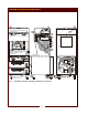
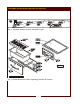
FEATURES & OPERATING CONTROLS 28 28 VENTILATOR CONTROL PANEL see pages 4 & 5 a15 28 1 56 53 19 16 18 a11 18 16 23 23 GRIDDLE CONTROL PANEL see pages 4 & 5 22 a10 ANS UL 40 12 IN CASE OF FIRE ® 41 PULL HANDLE TO ACTIV ATE FIRE SUPPRESSION SYST EM 44 a6 a31 43 WARMER CONTROLS see pages 4 & 5 8 9 Fig.
FEATURES & OPERATING CONTROLS (continued) VENTILATOR SECTION ITEM DESCRIPTION COMMENT 1. NAMEPLATE Lists Manufacturer, Model and Serial Number information. Also lists electrical specifications. a6. FIRE SUPPRESSION AGENT TANK (1.5 gal.) Container for Ansulex™ Low-pH liquid fire suppression liquid. 8. ADJUSTABLE (FRONT) LEG Allows the unit to be leveled. 9. RIGID (REAR) CASTER Allows the unit to be easily positioned by lifting the front of the unit slightly. a10.
FEATURES & OPERATING CONTROLS (continued) Fig. 2 Ventilator Section Controls & Indicator Lights Fig.
FEATURES & OPERATING CONTROLS (continued) ITEM DESCRIPTION COMMENT VENTILATOR SECTION CONTROLS V.01 POWER SWITCH Energizes blower motor. If, after 10 seconds, proper conditions are met, appliance is energized. V.02 POWER ON INDICATOR GREEN. Glows when POWER switch is ON. V.03 CHECK FILTERS ALARM INDICATOR AMBER. Glows if one or more filters are out of position. Check all filters and baffles for proper installation. V.04* REPLACE PREFILTER ALARM INDICATOR AMBER.
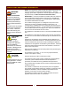
PRECAUTIONS AND GENERAL INFORMATION WARNING: Electric Shock hazard All servicing requiring access to non-insulated electrical components must be performed by a factory authorized technician. DO NOT open any access panel which requires the use of tools. Failure to follow this warning can result in severe electrical shock. CAUTION: Risk of Damage DO NOT connect or energize this appliance until all installation instructions are read and followed.
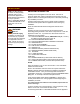
PRECAUTIONS AND GENERAL INFORMATION (continued) OPERATIONAL NOTES: REPLACE PREFILTER and REPLACE FILTER PACK indicator lights provide a timely warning that a system shut-down is imminent. The actual time between the indicator light coming on and the loss of cooking appliance power will depend upon the cooking conditions. Anytime a dirty PRE-FILTER is replaced, the system airflow will increase. If the condition of the FILTER PACK is marginal, the REPLACE FILTER PACK light could then come on.
INSTALLATION NOTE: DO NOT discard the carton or other packing materials until you have inspected the appliance for hidden damage and tested it for proper operation. Refer to SHIPPING DAMAGE CLAIM PROCEDURE on the inside front cover of this manual. WARNING: Risk of personal injury Installation procedures must be performed by a qualified technician with full knowledge of all applicable electrical codes. Failure can result in personal injury and property damage.
INSTALLATION (continued) SERVICE TECHNICIAN INSTALLATION NOTES An Ansul® technician must charge and arm the fire suppression system before the ventilator blower will operate. See page 10. Installation and start up must be performed by an Authorized Installation Company. Installer must complete the WARRANTY REGISTRATION form, and record appliance installation particulars on the CUSTOMER SERVICE DATA form in this manual. Certain codes require cooking equipment to be restrained with a RESTRAINT DEVICE.
INSTALLATION (continued) DANGER FIRE HAZARD FIRE SUPPRESSION SYSTEM INSTALLATION 1. Any REMOTE MANUAL PULL STATION must be installed by an authorized ANSUL® distributor in accordance with the AUTHORITY HAVING JURISDICTION. NOTE: If a REMOTE MANUAL PULL STATION is installed, moving the unit for servicing will cause the Ansul® system to discharge. In this case, the unit must only be installed with four fixed legs (i.e. remove rear casters and replace with legs).
INSTALLATION (continued) FILTERS INSTALLATION 1. FILTER PACK: Ships installed in the hood. If the FILTER PACK is not in position, the CHECK FILTERS indicator will light. If the FILTER PACK becomes clogged, the REPLACE FILTER PACK indicator will glow. To install the FILTER PACK: Position the filter pack with the charcoal portion UP. Slide the filter pack toward the rear of the unit until it contacts the guides on the back panel.
INSTALLATION (continued) WARNING Slipping / Falling Hazard Spilled Oil GREASE TROUGH AND GREASE CUP INSTALLATION 1. Install the GREASE TROUGH into the brackets below the grease baffle. 2. Install the GREASE CUP on the right side of the unit, directly below the grease trough. GRIDDLE INSTALLATION Install GREASE DRAWER in place under the griddle. ROLL WARMER INSTALLATION 1. Install roll warmer drawers in drawer slides. DO NOT OPERATE UNLESS THE GREASE CUP TROUGH AND GREASE DRAWER ARE INSTALLED.
OPERATION CAUTION: VENTILATOR OPERATION 1. Press the VENTILATOR POWER switch to ON. The green VENTILATOR POWER light will glow and the blower fan will start. After a short time, if all filters are sensed as being in position and not clogged, the griddle will be energized. The roll warmer is energized at all times. During normal operation, the VENTILATOR POWER light will be the only light glowing on the upper control panel. Hot Surface Exposed surfaces can be hot to the touch and may cause burns. 2.
OPERATION (continued) CAUTION: Hot Surface Exposed surfaces can be hot to the touch and may cause burns. As manufactured, the steel surface of your Wells griddle has microscopic pores. It is important to fill these pores with oil in order to provide a hard, non-stick cooking surface. Because the microscopic pores in the griddle surface are filled by the chrome plating, no seasoning of the griddle surface is required.
OPERATION (continued) CAUTION: DRAWER WARMER OPERATION (when provided) Hot Surface HEATING OPTIONS 1. Moist heat with Humitrol Rack: a. MOIST operation prevents food from drying out as moisture, as well as heat, is applied to the warming chamber. b. To set for MOIST operation, remove Humitrol Rack from bottom of drawer insert pan and carefully pour approximately 2 quarts of water (½” depth) into the pan. Reinstall rack. c.
CLEANING INSTRUCTIONS CAUTION: Electric Shock Hazard Disconnect appliance from electric power before cleaning. GRIDDLE DAILY CLEANING PREPARATIONS: Set temperature control to 220ºF. Allow the griddle temperature to drop to 220ºF before proceeding.
CLEANING INSTRUCTIONS (continued) CAUTION: VENTILATOR WEEKLY CLEANING ROLL WARMER WEEKLY CLEANING PREPARATION: Disconnect appliance from electric power Allow to cool before cleaning FREQUENCY: Weekly TOOLS: Warm water and a mild detergent Soft clean cloth or sponge Bristle brush Container for disposal of grease VENTILATOR SECTION Remove the grease baffle, pre-filter assembly, grease trough and grease cup. Empty the grease trough and grease cup. Remove the pre-filter from the filter frame.
CLEANING INSTRUCTIONS CAUTION: VENTILATOR MONTHLY CLEANING Electric Shock Hazard PREPARATION: Disconnect appliance from electric power Allow to cool before cleaning FREQUENCY: Monthly TOOLS: Warm water and a mild detergent Soft clean cloth or sponge Plastic scouring pad, plastic scraper Container for disposal of grease Disconnect appliance from electric power before cleaning. CAUTION: Hot Surface EXTERIOR Exposed surfaces can be hot to the touch and may cause burns.
MAINTENANCE SCHEDULES 1. 6-MONTH MAINTENANCE (MUST BE PERFORMED BY AN AUTHORIZED ANSUL® DISTRIBUTOR ONLY): a. Inspect and test total operation including FIRE DAMPER and all SAFETY INTERLOCKS. b. All FIRE SUPPRESSION SYSTEM actuation components including MANUAL PULL STATION and any REMOTE MANUAL PULL STATION must be inspected for proper operation in accordance with the maintenance schedule published in ANSUL® R-102 SYSTEM DESIGN, INSTALLATION, RECHARGE AND MAINTENANCE MANUAL (Ansul® #418087-05). c.
20
21
ANSUL® MATERIAL SAFETY DATA SHEET ANSUL INCORPORATED MARINETTE, WI 54143-2542 ANSULEX Low pH QUICK IDENTIFIER (In Plant Common Name) Manufacturer’s Name: ANSUL INCORPORATED Emergency Telephone No.
ANSULEX Low pH (continued) SECTION 5 - HEALTH HAZARDS Threshold Limit Value: None Established Routes of Entry: Eye Contact: Irritant Skin Contact: Irritant Inhalation: Not an expected route of entry. Can be irritating to mucous membranes. Ingestion: Irritating to mucous membranes. Acute Oral LD50 (Sprague-Dawley rats) 825.5mg/kg. Acute Exposure: Material irritates skin, eyes, and mucous membranes. Chronic Exposure: None known.
TROUBLESHOOTING SUGGESTIONS SYMPTOM POSSIBLE CAUSE SUGGESTED ACTION Ventilator blower won’t run Circuit breaker tripped Check / reset circuit breaker Ventilator blower won’t run — buzzer sounding Ansul® fire suppression system tripped Contact Authorized Ansul® Distributor for repairs Ventilator blower runs momentarily, shuts down.
PARTS & SERVICE DESCRIPTION SERVICE PART NO. PRE-FILTER PRE-FILTER CAGE FILTER PACK (HEPA + CHARCOAL) GREASE BAFFLE LEG KIT CASTER KIT GREASE CUP SCRAPER, GROOVED GRIDDLE DRAWER PAN, REPLACEMENT RACK, HUMITROL 22618 22683 22619 22684 22649 22650 22626 20651 21488 20624 WELLS BULLETIN (ANSUL® PARTS LIST) NOTE: Ansul® Manual 418087-05 and Wells Bulletin 303331 are intended for use by authorized Ansul® service personnel only.