
Service manual


PAGE 4-4 SERVICE MANUAL WG-xxG Series Gas Griddles SERVICE
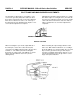
PILOT FLAME AND MAIN BURNER ADJUSTMENTS
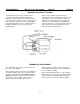
The pilot flame is adjusted by a screw under a cover
screw on the gas valve (# 25) above and to the left of
the pointer for the plastic knob on the valve. Adjust the
flame level so that it covers 3/8" to 1/2" of the top of
the thermopile (See the drawing below). Replace cover
screw after the adjustment is complete.
Adjusting the main burner air/fuel mixture for a steady
blue flame requires loosening the 5/16" (A small 5/16"
box wrench is required) hex head screw on the shutter
collar at the throat of the burner, rotate the shutter to
adjust, re-tighten the set screw after adjustment is
completed.
CORRECT FLAME LEVEL THERMOPILE
OUTPUT VOLTAGE
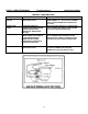
When measuring the open circuit output millivolts of
the thermopile, set the valve control knob to pilot,
connect the test (Milli)-Voltmeter leads to the gas valve
terminals "1 & 2", with the pilot flame heating the
thermopile, an output of 500 - 600 millivolts is normal
with no load other than the test meter. (See the
drawing below).
When measuring the output voltage with the control
valve set to "ON" and the main burner on, a reading of
about 325 millivolts is a normal reading. An occasional
drop-out of the gas flow from the gas valve may be
caused by a marginal output voltage (200 mV or less)
of the thermopile that causes the gas valve to cut off
all gas to the pilot and burner.
12