
Service manual


SERVICE MANUAL WG-xxG Series Gas Griddles SERVICE PAGE 4-3
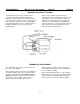
REPLACING PILOTS AND THERMOPILES
Access to pilots and or thermopiles is from below
the griddle. The pilots (#42) are mounted from
below to the main frame assembly by 2 phillips
truss head screws.
The thermopiles are screwed into the bottom of
the pilot bracket by a 7/16" hex bushing. The
thermopile may be removed with the pilot
mounted to the frame.
REPLACING PILOT ORIFICES
When cleaning or replacing pilot burner (#42)
orifices, the orifice is held in place between the
pilot tube (# 21, 22. or 23) and flame deflector
tube by a hex nut from below the mounting
bracket.
Access to the pilot orifice mounting nut is from
the bottom of the griddle. In some cases the pilot
tube mounting nut on the gas valve may require
loosening to get the tube out of the pilot
assembly.
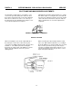
REPLACING BURNER ORIFICES
To clean or replace the main burner orifices, the
following instructions will gain access to the
orifices.
Each main burner orifice (# 28) is mounted to a
bracket (# 16) by a brass fitting (# 27) at the end
of the burner feed tubing (#31, 32, or 33). Loosen
the fitting (# 27) from feed tube, remove the hex
nut (# 17) that mounts bracket (# 16) to the main
frame (# 1), remove the bracket/fitting and orifice
from the throat of the burner assembly.
Support the brass flange elbow fitting (# 27) and
remove the burner orifice (# 28) by un-screwing it
counter-clockwise from the elbow fitting.
When re-assembling, sparingly apply a pipe dope
coating to the male threads of the elbow (On LPG
units use only a dope that is approved for use
with LPG fuel).
When placing the assembly back on the main
frame, be sure the orifice/bracket and burner
throat alignment is straight down the center of the
burner and that the burner is still in place with its
guide pins at the rear and end properly located to
align the burner correctly.
Be sure to leak check all gas line fittings with a
soap and water or other approved solution after
working on the gas lines.
REPLACING REGULATOR ASSEMBLY
Always support the manifold assembly (# 34) to avoid
damage to the manifold or fittings and lines attached
to it when removing or replacing the regulator (# 38)
assembly. Always clean off old pipe dope and
sparingly re-coat male threads only with an approved
pipe dope for the type of fuel used. The regulator body
should be mounted so that the vent is pointing down
so as to limit the possibility of being contaminated with
air born grease.
Support the manifold with a pipe wrench and use
tight fitting adjustable or open end wrench on the
hex of the regulator (Always place the wrench at
the end that is being removed/installed to the
piping) where it connects to the manifold. Be sure
the pipe and regulator are free of dirt and other
contamination.
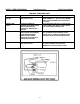
MAIN BURNER SERVICE
Removing/replacing U shaped (# 5) main burners
require removing the rear flue assemble (# 3) from the
main frame assembly. Main burners are held in place
by a threaded pin at the lower side in the
center of the U bend of the burner set in a hole in
the rear of the main frame and by the shutter
collar slipped over the orifice at the front and are
leveled by a pin on the frame at the end of the
burner.
11