SERVICE MANUAL WG SERIES GAS GRIDDLES WELLS MANUFACTURING COMPANY Revision 04/15/93 Replaces Preliminary Manual Dated 12/17/91 P.O. Box 280 VERDI, NV.
Data sheets and text of this manual are representative of current production models as of 12/17/91. Specifications, Model Number designations and data are subject to change at any time without notice! CAUTION: NEVER SUBMERGE ELECTRICAL EQUIPMENT IN WATER. AVOID CONTAMINATING ELECTRICAL COM PONENTS WITH MOISTURE WHEN CLEANING CABINET SURFACES.
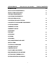
SERVICE MANUAL WG-xxG Series Gas Griddles TABLE OF CONTENTS INTRODUCTION 1-1 INSTALLATION REQUIREMENTS 1-1 INSTALLATION CLEARANCES 1-1 VENTING REQUIREMENTS 1-1 GAS PIPING REQUIREMENTS: PRESSURE REGULATOR 1-1 GAS PIPING PRESSURE TESTING 1-2 GAS SUPPLY FLOW/VOLUME REQUIREMENT 1-2 LEVELING GRIDDLE 1-2 WARRANTY STATUS 1-2 WARRANTY NOTICE 1-3 OPERATION: PURPOSE 2-1 OPERATION 2-1 CLEANING 2-1 SEASONING 2-1 DAILY MAINTENANCE AND CARE 2-1 INSTALLATION: TESTING GAS PRESSURE 3-1 PUR
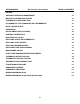
SERVICE MANUAL WG-xxG Series Gas Griddles TABLE OF CONTENTS SERVICE: CONTROL CALIBRATION REQUIREMENT 4-1 IMPORTANT CALIBRATION CAUTION 4-1 THERMOSTAT CAUBRATION TOOL 4-1 PLACEMENT OF TEST PYROMETER OR THERMOMETER 4-1 INITIAL HEATING CYCLE 4-1 CAUBRATION 4-1 REPLACEMENT PARTS CAUTIONS 4-2 CONTROL THERMOSTATS 4-2 REPLACING GAS VALVES 4-2 REPLACING PILOTS AND THERMOPILES 4-3 REPLACING PILOT ORIFICES 4-3 REPLACING BURNER ORIFICES 4-3 REPLACING REGULATOR ASSEMBLY 4-3 MAIN BURNER SERV
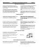
SERVICE MANUAL WG-xxG Series Gas Griddles Introduction PAGE 1-1 INTRODUCTION Wells Heavy Duty, High Performance WG Series Gas Griddles are designed to cook a full range of food items, from eggs to steaks. Grills effectively at both low and high temperatures for maximum versatility. Fully controllable from 200" F. to 450' F. These Gas Griddles are available in Natural Gas and Propane versions. WG2436G, a 36" x 25%" Cooking Surface, 75,000 BTU per hour rated. WG3036G.
PAGE 1-2 SERVICE MANUAL WG-xxG Series Gas Griddles Introduction GAS PIPING REQUIREMENTS Cont Supply piping should be a minimum of % inch black iron pipe with a sediment trap (drip leg) consisting of a pipe tee, 4" nipple with cap to prevent dirt from entering the control valves (Consult local codes and ordinances for guidance for this requirement, or in the absence of local codes, use the National Gas Code ANSI Z223.1 and NFPA No. 54).
Service Manual WG-xxG Series Griddles Introduction PAGE 1-3 WARRANTY SERVICE PROVIDED AT THE CUSTOMERS JOB SITE IS LIMITED TO A 60 MILE RADIUS FROM THE CLOSEST WELLS AUTHORIZED SERVICE COMPANY LOCATION AND MUST BE PERFORMED DURING SERVICE WORKING HOURS. ADDITIONAL TRAVEL TIME, MILEAGE, AND LABOR CHARGES ARE THE END USERS RESPONSIBILITY. CALIBRATION 60 DAYS FROM THE DATE OF INSTALLATION.
SERVICE MANUAL GW-xxG Series Gas Griddles Operation PAGE 2-1 OPERATION PURPOSE Wells WG Series Griddles provide a heavy duty gas fired platen for grilling food products. To set the desired cooking temperatures the front panel covering the control thermostats must be lowered to expose the control knobs. Variations in cooking surfaces include grooved segments in multiples of 6 inches to provide a charbroiled appearance to the meat when cooking.
SERVICE MANUAL WG-xxG Series Gas Griddles Installation PAGE 3-1 TESTING GAS PRESSURE Ports for measuring outlet gas pressure are located on the end of each valve below the red terminal block, a port (# 40 Plug) is also available on the manifold. The regulator Has an adjustment screw under the cap at the raised center of the body of the regulator. Outlet pressure is factory set at the regulator manufacturer for 5 inches (W.C.) for Natural Gas and 10 inches (W.C.) for Propane Gas.
PAGE 3-2 SERVICE MANUAL WG-xxG Series Gas Griddle Installation SETTING ZONE THERMOSTATS Each heated zone of the cooking surface has a snap action thermostat to control the gas valve for that section. Access to set each control knob is by lowering the front panel. After the pilots have been lighted and proven established, turn rotate the knob to the desired (200* to 450° F.) temperature.
SERVICE MANUAL WG-xxG Series Gas Griddles SERVICE PAGE 4-1 CONTROL CALIBRATION REQUIREMENT WG-2424G to WG-3048G SERIES GRIDDLES Calibration should not be attempted if the dial can be adjusted to compensate for the temperature variation, or, if the actual griddle surface temperature varies from the dial setting by more than 125° F. Variations of less than ± 25° F. should be compensated for by adjusting the control dial up or down to the desired surface temperature.
PAGE 4-2 SERVICE MANUAL WG-xxG Series Gas Griddles_ ________SERVICE REPLACEMENT PARTS CAUTIONS When replacing the control thermostats, thermopiles, pilots, and control valves, be sum them is no possibility of hot electrical terminals touching the capillary tubes, case, or other conductive parts. Be sum to dean and re-dope all pipe thread connections. Apply dope only to the mate threads when assembling pipe fittings. Always do a thorough teak check after working on threaded fittings.
SERVICE MANUAL WG-xxG Series Gas Griddles SERVICE PAGE 4-3 REPLACING PILOTS AND THERMOPILES Access to pilots and or thermopiles is from below The thermopiles are screwed into the bottom of the griddle. The pilots (#42) are mounted from the pilot bracket by a 7/16" hex bushing. The below to the main frame assembly by 2 phillips thermopile may be removed with the pilot truss head screws. mounted to the frame.
PAGE 4-4 SERVICE MANUAL WG-xxG Series Gas Griddles SERVICE PILOT FLAME AND MAIN BURNER ADJUSTMENTS The pilot flame is adjusted by a screw under a cover screw on the gas valve (# 25) above and to the left of the pointer for the plastic knob on the valve. Adjust the flame level so that it covers 3/8" to 1/2" of the top of the thermopile (See the drawing below). Replace cover screw after the adjustment is complete.
SERVICE MANUAL WG-xxG Series Gas Griddles SERVICE PAGE 4-5 THERMOSTAT CONTACT TESTING Testing the thermostat for open contacts can be accomplished by simply placing a jumper wire between test point 1 and 3 on the gas valve terminal block. When these two points are connected, the gas valve should open and the main burner should light provided the pilot flame has been established prior to placing the jumper on the test points. (See the drawing below).
SERVICE MANUAL Troubleshooting Guide Gas Griddles ___ _____PAGE 5-1 TROUBLE SYMPTOM CHART TROUBLE SYMPTOM CHART PROBLEM PROBABLE CAUSE CORRECTIVE ACTION ALL PILOTS WILL NOT LIGHT GAS SUPPLY TURNED OFF TURN ON GAS TO GRIDDLE.
PAGE 5-2 SERVICE MANUAL Troubleshooting Guide Gas Griddles TROUBLE SYMPTOM CHART PROBLEM PROBABLE CAUSE CORRECTIVE ACTION BURNER WILL NOT SHUT OFF DEFECTIVE THERMOSTAT, DEFECTIVE GAS VALVE DISCONNECT WIRE BETWEEN THERMOSTAT AND LOWER TERMINAL "# 3" ON GAS VALVE; IF BURNER STOPS, REPLACE THERMOSTAT; IF NOT REPLACE GAS VALVE.
PAGE 5-4 SERVICE MANUAL Troubleshooting Guide Component Pictorial 18 Gas Griddles
SERVICE MANUAL ? = VARIES BY WIDTH OF UNIT ITEM NUMBER PART NUMBER WG-xxG Series Gas Griddles F/O = FACTORY ORDER PAGE 6-1 L/P = LOCAL PURCHASE COMPONENT DESCRIPTION A/R = AS REQUIRED N/S = NOT SHOWN QTY 1 FRAME ASSEMBLY, MAIN 1 2 TOP ASSEMBLY 1 3 FLUE ASSEMBLY 1 PANEL, SIDE 4 NOTES: 5a 65303 BURNER ASSEMBLY, MAIN 2 ? 3 TO 4 REQ. 5b 65302 BURNER ASSEMBLY, MAIN (WG-3036^048: ? 2 TO 3 REQ. 2 TO 3 REQ. 6a 65951 HOLDER.
PAGE 6-2 SERVICE MANUAL ? = VARIES BY WIDTH OF UNIT F/O = FACTORY ORDER WG-xxG Series Gas Griddles L/P = LOCAL PURCHASE A/R = AS REQUIRED N/S = NOT SHOWN ITEM NUMBER PART NUMBER 31 65316 TUBE.
SERVICE MANUAL ? = VARIES BY WIDTH OF UNIT WG-xxG Series Gas Griddles F/O= FACTORY ORDER L/P= LOCAL PURCHASE PAGE 6-3 A/R = AS REQUIRED N/S = NOT SHOWN ITEM NUMBER PART NUMBER 60 65292 PANEL. FRONT UPPER 1 61 53453 CATCH, MAGNETIC 2 62 LABEL.
SERVICE MANUAL WG-xxG Series Gas Griddles Wiring diagram WG-2436G, WG-3036G PN: 45355 Wiring diagram WG-3048G PN: 45356 22 PAGE 6-4