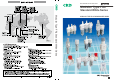
Now available in new white color Modular Type FRL Standard White Series Modular Type FRL Standard White Series MODULAR TYPE FRL STANDARD WHITE SERIES CC-962A 2
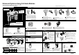
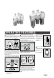
Enhanced Systems Using Full-Scale Modules 6\VWHPV DUH HDVLO\ XSJUDGHG XVLQJ XQL¿HG NH\ GLPHQVLRQV and a diverse range of options and variations. Combination * Indicates series model no. 1, 2, 3, 4, 5, 6, 7, 8. This page shows only the outline. Refer to contents later in this catalog for details. Mounting bracket Page 152 "C*000-W" FRL combination. Lubricator "L*000-W" Supplies oil mist to pneumatic lines.
Series variation F.R.L. unit (Combination) F Filter F.R.L. combination P.21 WL combination R Regulator Lubricator Modular type FRL P.35 FMR combination P.41 WM combination P.
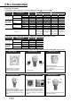
Series variation F.R.L. unit (Filter regulator) Series Modular type Filter regulator 5HYHUVH ¿OWHU regulator Model no. Port size 1/8 1/4 3/8 1/2 3/4 1 W1000-W W2000-W W3000-W W4000-W W8000-W W1100-W W2100-W W3100-W W4100-W W8100-W Page 69 77 (Filter) Series Modular type Filter $LU ¿OWHU medium pressure Model no.
Series variation F.R.L. unit (Other related components/attachments) (Other related components) Series Model no.
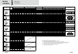
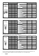
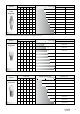
Port size Series Maximum flow rate m 3/min. (ANR) 1/8 1/4 3/8 1/2 3/4 1 ● ● ● ● ● ● FRL Combination 0.1 Automatic drain C1000-6-W - C1000-8-W - C2000-8-W C2000-8-W-F1 1.7 C2000-10-W C2000-10-W-F1 1.28 C3000-8-W C3000-8-W-F C3000-10-W C3000-10-W-F C4000-10-W C4000-10-W-F C4000-15-W C4000-15-W-F C8000-20-W C8000-20-W-F C8000-25-W C8000-25-W-F 10 0.45 0.63 ● ● Manual drain 1.0 ● 1.2 ● Model no. 1.75 2.4 3.0 7.0 7.5 *Flow rate when supplied pressure is 0.
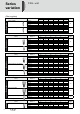
Port size Series Maximum flow rate Model no. m 3/min. (ANR) 1/8 1/4 3/8 1/2 3/4 1 ● ● ● ● ● ● Filter Regulator 0.1 1.0 Manual drain Automatic drain W1000-6-W - 1.15 W1000-8-W - ● 1.5 W2000-8-W W2000-8-W-F1, Note 1 ● 2.0 W2000-10-W W2000-10-W-F1, Note 1 W3000-8-W W3000-8-W-F W3000-10-W W3000-10-W-F 4.35 W4000-10-W W4000-10-W-F 4.75 W4000-15-W W4000-15-W-F 10.0 W8000-20-W W8000-20-W-F 10.0 W8000-25-W W8000-25-W-F 0.83 ● ● 10 2.15 2.
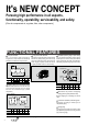
It's NEW CONCEPT Pursuing high performance in all aspects, functionality, operability, serviceability, and safety. >)LOWHU IRU FRPSUHVVHG DLU UHJXODWRU ¿OWHU RWKHU FRPSRQHQWV@ FUNCTIONAL FEATURES Compact module Long service life element F.R.L. main dimensions (width and depth) are integrated into a compact module. Accurate assembly dimensions are obtained with simple calculation.
OPERATIVE FEATURES 2LO GULS DGMXVWPHQW NQRE ZLWK ORFN Tool free pressure control 1R WRROV UHTXLUHG WR DGMXVW SUHVVXUH 7KH NQRE LV ORFNHG with a single push, The knob is locked with a single push, and is easily operated when setting pressure. TOOL-FREE SETTING F.R.L. R1000-W R2000-W R3000-W R4000-W R6000-W R8000-W (DV\ WRRO IUHH RLO GRVLQJ DGMXVWPHQW $ stopper is provided in the opening direction to function as a lock, and increase safety.
F.R.
F.R.
Safety precautions Always read this section before starting use. When designing and manufacturing a device using CKD products, the manufacturer is obligated to check that device safety mechanism, pneumatic control circuit, or water control circuit and the system operated by electrical control that controls the devices is secured. It is important to select, use, handle, and maintain the product appropriately to ensure that the CKD product is used safely.
Pneumatic components (F.R.L. unit (modular design)) Safety precautions Always read this section before starting use. 5HIHU WR ³3QHXPDWLF 9DFXXP DQG $X[LOLDU\ &RPSRQHQWV &DWDORJ 1R &% 6$ ´ SUHFDXWLRQV IRU SQHXPDWLF FRPSRQHQWV LQ JHQHUDO 6SHFL¿F SUHFDXWLRQV ) 5 / PRGXODU GHVLJQ Design & Selection WARNING 1. Common WARNING This product is for industrial use only. It must not be used in components or circuits for medical equipment or components that involve human lives.
F.R.L. unit (modular design) 5HJXODWRU ¿OWHU ZLWK UHJXODWRU WARNING Install a safety device where an output pressure H[FHHGLQJ WKH UHJXODWRU V VHW SUHVVXUH YDOXH FRXOG result in damage or faulty operation of secondary side devices. The regulator cannot process residual pressure (remove secondary pressure) when primary pressure is released. Use a regulator with a check valve when residual pressure must be processed. 5.
F.R.L. unit (modular design) 6SHFL¿F SUHFDXWLRQV Installation & Adjustment Drain piping 1. Common CAUTION YRLG LQVWDOOLQJ WKLV SURGXFW ZKHUH LW LV VXEMHFW WR $ direct UV rays. Flush and wash pipes to be used. Dirt or foreign materials in piping will lower product performance. Check that foreign materials do not enter when WLJKWHQLQJ SLSHV RU MRLQWV :KHQ VFUHZLQJ LQ SLSLQJ RU MRLQWV FKHFN WKDW VZDUI IURP piping threads or sealing agent does not get inside.
F.R.L. unit (modular design) 5HJXODWRU ¿OWHU ZLWK UHJXODWRU CAUTION CAUTION 5HJXODWRU ¿OWHU UHJXODWRU $GMXVWPHQW RI OXEULFDWRU RLO GULSSDJH Lightly tighten (0.6 N·m or less) mounting screws for embedded pressure gauge G401-W-OP, G401-W, and gauge plug. When installing the pressure gauge with a safety mark on the gauge plug, or when installing a general screw-in pressure gauge, tighten with a torque of 15N·m or less. 'R QRW PRYH RU VZLQJ WKH SURGXFW KROGLQJ WKH DGMXVWPHQW knob on the regulator.
F.R.L. unit (modular design) 6SHFL¿F SUHFDXWLRQV Installation & Adjustment Install vertically so the scale can be seen right from the front. (Refer to drawing below) Installation on other position will result in an unstable movement of the indicator and lower accuracy. 5.
F.R.L. unit (modular design) LO PLVW ¿OWHU 2 The service lif of the mantle (element) is 1 year (6000 hours) or when SUHVVXUH GURSV WR 03D ([FHSW IRU WKH ; W\SH 5HSODFH WKH PDQWOH ZKHQ life is reached. (Do not touch the urethane foam layer during replacement.) Removing metal bowl 2000-W, 3000-W, 4000-W, 6000-W, 8000-W Series Replace the element before the differential pressure indicator becomes all read if it has an differential pressure indicator.
F.R.L. unit (modular design) 6SHFL¿F SUHFDXWLRQV 6SHFL¿F SUHFDXWLRQV ) 5 / FRPSRQHQWV Chemical resistance of plastic parts WARNING The chemical resistance of plastic parts are shown below. Avoid using products in an atmosphere where chemicals are contained in compressed air, the atmosphere, or where they could adhere to parts. Use in this state could lead to bowl damage and accidents. Avoid using these types of chemicals or in an atmosphere containing these chemicals.
F.R.L. unit (modular design) Precautions for each model Automatic drain DT3000 DT4000-W Series Installation & Adjustment CAUTION Piping, load torque Piping screw-in torque 'R QRW DSSO\ H[FHVVLYH WRUTXH WR WKH ERG\ DQG SLSLQJ ZKHQ connecting pipes. 3000 4000 Series 0D[ WRUTXH 1 m 3000 4000 Series 0D[ WRUTXH 1 m Make sure that piping load or torque is not applied on the body or piping.
Modular type Standard white series Components for air preparation/F.R.L. unit C O N T E N T S Product introduction Series variation Product description Safety precautions Intro 1 1 to 6 7 to 10 11 to 18 Combination F.R.L. combination (C*000-W) W.L. combination (C*010-W) F.R. combination (C*020-W) F.M.R. combination (C*030-W) W.M. combination (C*040-W) R.M. combination (C*050-W) F.M. combination (C*060-W) F.F.M.
F.R.L.
F.R.L. Combination How to order How to order 5HIHU WRS SDJH IRU DQ H[SODQDWLRQ RI WKH RSWLRQV Note 1 & 6\PERO Model no.
F.R.L.
0(02 24
F.R.L.
F.R.L.
F.R.L.
F.R.L.
F.R.L.
W.L.
W.L.
W.L.
W.L.
W.L. Combination Dimensions with options Dimensions with options A & : WR & : Model no. A B & : B & : & : & : & : L1 L2 L3 Assembled options Model no.
F.R.L.
F.R.
F.R.
F.R.
F.R.
F.R.
) 0 5 FRPELQDWLRQ VWDQGDUG ZKLWH VHULHV C1030 / C2030 / C2530-W C3030 / C4030 / C6030 / C8030-W Series ,QWHJUDWHG ¿OWHU RLO PLVW ¿OWHU DQG UHJXODWRU Port size: 1/8 to 1 -,6 V\PERO 6SHFL¿FDWLRQV Descriptions C1030-W C2030-W C2530-W C3030-W C4030-W C6030-W C8030-W ([WHULRU )LOWHU &RPSRQHQWV 2LO PLVW ¿OWHU 5HJXODWRU ) : ) : ) : ) : ) : ) : ) : 0 : 0 : 0 : 0 : 0 : 0 : 0 : 5 : 5 : 5 : 5 : 5 : 5 : 5
F.M.R.
F.M.R.
F.M.R.
F.M.R.
F.M.R.
: 0 FRPELQDWLRQ VWDQGDUG ZKLWH VHULHV C1040/C2040/C3040/C4040/C8040-W Series ,QWHJUDWHG ¿OWHU RLO PLVW ¿OWHU DQG UHJXODWRU Port size: 1/8 to 1 -,6 V\PERO 6SHFL¿FDWLRQV Descriptions C1040-W C2040-W C3040-W C4040-W C8040-W )LOWHU UHJXODWRU : : : : : : : : : : 2LO PLVW ¿OWHU 0 : 0 : 0 : 0 : 0 : ([WHULRU &RPSRQHQWV :RUNLQJ ÀXLG &RPSUHVVHG DLU 0D[ ZRUNLQJ SUHVVXUH 03D 1 :LWKVWDQGLQJ SUHVVXUH 03D $PELHQW WHPSHUDWXUH UDQJH 6HW SUHVVXUH
W.M.
W.M.
W.M.
W.M.
W.M. Combination Dimensions with options Dimensions with options & : WR & : Model no. A B & : A & : & : B & : L1 & : L2 L3 Assembled options S P V K SV SK PV PK Model no.
R.M.
R.M. Combination How to order & & & 5HIHU SDJH IRU DQ H[SODQDWLRQ RI the options. A6W L & W & 6 A Model no. & C1050 & How to order 'HVFULSWLRQV Symbol B Port size A Model no.
R.M.
R.M.
R.M.
R.M.
F.M.
F.M. Combination How to order How to order 6 W Z 5HIHU SDJH IRU DQ H[SODQDWLRQ RI WKH RSWLRQV A6W 'HVFULSWLRQV Symbol A Model no. B Port B Port size size & Port & & & & & & C1060 A Model no.
F.M.
F.M.
F.M.
MEMO 64
F.F.M.
F.F.M. Combination How to order How to order 'HVFULSWLRQV Symbol A Model no. B Port B Port size size 8 1/4 10 3/8 15 1/2 20 3/4 25 1 1RWH & Port thread type & & 5HIHU SDJH IRU DQ H[SODQDWLRQ RI WKH RSWLRQV A6W Z & W & 6 & C3070 A Model no.
F.F.M.
F.F.M.
Filter regulator Standard white series W1000/W2000/W3000/W4000/W8000-W Series ,QWURGXFLQJ WKH P GXVW UHPRYLQJ HOHPHQW DQG m tar removing element to the lineup Port size: 1/8 to 1 JIS symbol 6SHFL¿FDWLRQV Descriptions W1000-W W2000-W W3000-W W4000-W W8000-W Exterior :RUNLQJ ÀXLG &RPSUHVVHG DLU 0D[ ZRUNLQJ SUHVVXUH 03D 1RWH Withstanding pressure MPa 1RWH WR Ambient temperature range Set pressure range MPa RU WR
Filter Regulator Series How to order : A6W Z : W : W1000 6 A Model no. : How to order : 5HIHU SDJH IRU DQ H[SODQDWLRQ RI WKH RSWLRQV 'HVFULSWLRQV Symbol B Port size B A Model Port size no.
Filter Regulator Series Flow characteristics 03D $LU ÀRZ UDWH P3 PLQ $15 Secondary pressure Secondary pressure 3ULPDU\ SUHVVXUH 03D 1 2 3ULPDU\ SUHVVXUH 03D 03D 03D 3ULPDU\ SUHVVXUH 03D 1 2 3ULPDU\ SUHVVXUH 03D 03D 2 3 4 6 8 3UL
Filter Regulator Series Internal structure and parts list Internal structure and parts list : : : : 7 7 6 5 6 1 9 5 2 9 2 287 IN 10 287 IN 8 3 4 3 8 4 11 12 12 11 : : : : : : 7 7 6 6 8 9 5 IN 1 1 5 2 287 9 3 10 10 287 IN 4 2 11 3 4 8 12 12 11 No.
Filter Regulator Series Dimensions Attachment C type bracket (-BW) Part no: B120 40 40 2 35 IN Tube center With PPD Option Rc1/8 (6) Rc1/4 (8) 68 44 45 92 Attached pressure gauge Panel cut dimensions ø2 6. 5 M5 Drain port Panel thickness: Max. 6mm 3 Dimension for knob operation W2000-W 35.5 45 2.3 ø39 G49P (73.5) ø43.5 G59P (76) ø52 G40P (75.5) ø42.5 G50P (75.5) ø52.5 G41P (74) ø42 G52P (86) ø52.5 R2 (74) 30 69 54 38 18 45 2.3 ø17.3 7 33 41 Y 88.
Filter Regulator Series Dimensions Dimensions 45 Attachment C type bracket (-BW) part no.: B320 45 67 2.3 2.3 34.5 45 63.5 72 45 53.5 OUT Tube center IN Tube center Port size Rc1/4 (8) Rc3/8 (10) 67 34.5 Panel cut dimensions IN Tube center Panel thickness: Max. 4mm 31.5 60 The dimensions for the plastic bowl is the same wheather the manual drain cock or automatic drain is installed. X Y G45P (70) ø39 G49P (69.5) ø43.5 G59P (72) ø52 G40P (71.5) ø42.5 G50P (71.5) ø52.
Filter Regulator Series Dimensions X 61.5 50 Option dimensions 65 2.3 60 Inner diameter ø5.7 to ø6 soft nylon tube inner diameter ø5. soft vinyl tube Drain port Maintenance dimensions The dimensions for the plastic bowl is the same wheather the manual drain cock or automatic drain is installed. 50 (84.5) ø43.5 G59P (87) ø52 G40P (86.5) ø42.5 G50P (86.5) ø52.5 G41P (85) ø42 G52P (98) ø52.
MEMO 76
5HYHUVH ¿OWHU regulator Standard white series W1100/W2100/W3100/W4100/W8100-W Series Introducing the 5 m dust removing element and 0.3 P WDU UHPRYLQJ HOHPHQW ZLWK EDFN ÀRZ IXQFWLRQ WR WKH OLQHXS JIS symbol 6SHFL¿FDWLRQV Descriptions W1100-W W2100-W W3100-W W4100-W W8100-W Exterior :RUNLQJ ÀXLG Compressed air Max. working pressure MPa 1.0 Note 4, 5, 6 Withstanding pressure MPa 1.5 Note 6 Ambient temperature range 5 to 60 Note 7 m Filtration rating 5 5 or 0.3 0.05 to 0.
Filter Regulator Series How to order * Refer page 9 for an explanation of the options. A6W Symbol : Z : W : 6 : W1100 A Model no. : How to order Descriptions B Port size A Model no.
Filter Regulator Series Flow characteristics 0.6 0.5 0.4 0.3 0.2 0.1 (MPa) 0 0.5 1.0 1.5 Primary pressure 0.7 MPa 0.6 0.5 0.4 0.3 0.2 0.1 0.5 0.5 0.4 0.3 0.2 0.1 (MPa) 0.5 1 1.5 2 2.5 0.5 0.4 0.3 0.2 0.1 0 0.3 0.2 0.1 (MPa) 1.5 2.0 2.5 0.5 2.0 2.5 0.4 0.3 0.2 0.1 Primary pressure 0.7 MPa 0.4 0.3 0.2 0.1 2 3 4 5 6 7 8 0.1 (MPa) 0 0.6 9 10 3.0 2.0 4.0 2.0 3.0 4.0 Primary pressure 0.7 MPa 0.4 0.3 0.2 0.1 0 1.0 5.0 3.0 2.0 4.
Filter Regulator Series Internal structure and parts list Internal structure and parts list W1100-W W2100-W 7 7 1 6 5 6 10 2 9 5 IN OUT 2 8 3 10 OUT IN 9 8 3 4 4 12 11 11 12 W3100-W, W4100-W W8100-W 7 7 6 1 6 5 8 5 9 IN 1 10 2 9 OUT 8 3 10 4 2 11 4 3 12 12 11 Functional explanation Material No.
Filter Regulator Series Dimensions IN OUT 2 35 43.5 45 53.5 ø2 6. 5 2 Tube center Panel thickness: Max. 6mm Option dimensions With automatic drain (F1) With PPD option Tube center Port size Rc1/8 (6) Rc1/4 (8) Attachment (pressure gauge) 35.5 Maintenance dimensions L type bracket (-B3W) Part no: B130 Option dimensions with pressure gauge attached 68 44 45 OUT 90 G49P (73.5) ø43.5 G59P (76) ø52 G40P (75.5) ø42.5 G50P (75.5) ø52.5 G41P (74) ø42 G52P (86) ø52.
Filter Regulator Series Dimensions Dimensions W3100-W X 46.5 (34.5) 45 45 2.3 ø4 0 63.5 72 45 53.5 OUT Tube center 2.5 IN 2.3 Panel cut dimensions Y 104 3 Dimension for knob operation 103 63 148 Attachment A W (piping adaptor set) Inner diameter ø5.7 to ø6 soft nylon tube Inner diameter ø5 soft vinyl tube Port size Rc1/4 (8) Rc3/8 (10) Attachment (pressure gauge) 60 With PPD Option Drain port Panel thickness: Max. 4mm 31.
Filter Regulator Series Dimensions 170 Rc1 3/4: 176 4 100 Dimension for knob operation W8100-W X 61.5 50 65 Attachment C type bracket (-BW) Part no: B820 2.3 104 159 68 IN OUT Tube center 61 OUT 250 Port size Attachment (pressure gauge) Rc3/4 (20) Rc1 (25) Option dimensions with pressure gauge attached 50 60 With PPD (Option) Maintenance dimensions The dimensions for the plastic bowl is the same wheather the manual drain cock or automatic drain is installed.
Filter Regulator Series Option dimensions Option dimensions Metal bowl W2100-W W3100-W W4100-W W8100-W (option) With automatic drain (FM, F1M) Automatic drain cock (M) Tube center A B C Tube center Tube center Standard manual drain cock (M1) Dimensions table F1M M A B C W2100-W - - 147 W3100-W 163.5 143.5 154 W4100-W 187 166.5 177 W8100-W 266 245.5 256 Model no. Rc1/4 Drain port Drain port M1 Option, parts dimensions Bottom spring Looper 5 m element Y 0.
$LU ¿OWHU VWDQGDUG ZKLWH VHULHV F1000 / F2000 / F3000 F4000 / F6000 / F8000-W Series ,QWURGXFLQJ WKH P HOHPHQW IRU GXVW UHPRYDO DQG P HOHPHQW IRU WDU UHPRYDO P HOHPHQW VHULHV H[FOXGLQJ ) 6HULHV SRUW VL]H WR -,6 V\PERO 6SHFL¿FDWLRQV Descriptions F1000-W F2000-W F3000-W F4000-W F6000-W F8000-W 1RWH ([WHULRU :RUNLQJ ÀXLG &RPSUHVVHG DLU 0D[ ZRUNLQJ SUHVVXUH 03D 1RWH :LWKVWDQGLQJ SUHVVXUH 03D 1RWH $PELHQW WHPSHUDWXUH UDQJH WR
Air Filter Series +RZ WR RUGHU +RZ WR RUGHU 6 W Z 5HIHU SDJH IRU DQ H[SODQDWLRQ RI WKH RSWLRQV A6W 6\PERO A 0RGHO QR ) ) ) ) ) ) F1000 A Model no.
Air Filter Series )ORZ FKDUDFWHULVWLFV 03D 03D 03D 03D 03D 03D ) : 03D 03D $LU ÀRZ UDWH P PLQ $15 03D 03D 03D 03D 03D 3UHVVXUH GURS 03D ) : 03D 3UHVVXUH GURS 3UHVVXUH GURS ) : $LU ÀRZ UDWH P PLQ $15 $LU ÀRZ UDWH P PLQ $15 ) : ) :
Air Filter Series ,QWHUQDO VWUXFWXUH DQG SDUWV OLVW ,QWHUQDO VWUXFWXUH DQG SDUWV OLVW ) : ) : 1 287 IN 2 1 287 IN 3 2 3 4 4 5 5 6 6 ) : ) : ) : 1 1 287 IN 2 287 IN 2 3 3 4 4 5 5 6 6 ) : 1 2 287 IN 4 3 5 6 No.
Air Filter Series 'LPHQVLRQV ) : $WWDFKPHQW & W\SH EUDFNHW %: 3DUW QR % 287 IN 287 7XEH FHQWHU IN $WWDFKPHQW A : SLSLQJ DGDSWRU VHW 2SWLRQ GLPHQVLRQV :LWK DXWRPDWLF GUDLQ ) 3RUW VL]H 5F 5F 7XEH FHQWHU ,QQHU GLDPHWHU ¡ VRIW Q\ORQ WXEH 'UDLQ SRUW 0DLQWHQDQFH GLPHQVLRQV 0 'UDLQ SRUW ) : 0DLQWHQDQFH GLPHQVLRQV 'UDLQ SRUW ¡ 3RUW VL]H 5F 5F
Air Filter Series 'LPHQVLRQV 'LPHQVLRQV ) : 287 287 7XEH FHQWHU IN 3RUW VL]H 5F 5F $WWDFKPHQW A : SLSLQJ DGDSWRU VHW ,QQHU GLDPHWHU ¡ WR ¡ 6RIW Q\ORQ 7XEH ,QQHU GLDPHWHU ¡ 6RIW YLQ\O 7XEH IN $WWDFKPHQW & W\SH EUDFNHW %: 3DUW QR % 0DLQWHQDQFH GLPHQVLRQV 'UDLQ SRUW 7KH GLPHQVLRQV IRU WKH SODVWLF ERZO LV WKH VDPH ZKHDWKHU WKH PDQXDO GUDLQ FRFN RU DXWRPDWLF GUDLQ LV LQVWDOOHG 1RWH 7KH & W\
Air Filter Series 'LPHQVLRQV ) : 6HFRQGDU\ SUHVVXUH 5F $WWDFKPHQW & W\SH EUDFNHW %: 3DUW QR % 6HFRQGDU\ SUHVVXUH 5F 287 7XEH FHQWHU IN :LWK GLIIHUHQWLDO SUHVVXUH GHWHFWLRQ SRUW 5F 287 IN 3RUW VL]H 5F 5F $WWDFKPHQW A : SLSLQJ DGDSWRU VHW ,QQHU GLDPHWHU ¡ WR VRIW Q\ORQ WXEH ,QQHU GLDPHWHU ¡ VRIW YLQ\O WXEH 'UDLQ SRUW 0DLQWHQDQFH GLPHQVLRQV ) : $WWDFKPHQW
Air Filter Series 2SWLRQ GLPHQVLRQV 2SWLRQ GLPHQVLRQV 0HWDO ERZO ) : ) : ) : ) : ) : RSWLRQ 0HWDO PDQXDO FRFN :LWK DXWRPDWLF GUDLQ ) 0 7XEH FHQWHU 3LSLQJ FHQWHU C A B 7XEH FHQWHU 6WDQGDUG PDQXDO GUDLQ FRFN 0 :LWK SHWFRFN 0 PRESS TURN 5F 'UDLQ SRUW 'UDLQ SRUW 'LPHQVLRQV WDEOH Model no.
Air Filter Series 2SWLRQDO SDUWV GUDZLQJ (OHPHQW Element model no. Model 5 m Element 0.
Air Filter Series %RZO DVVHPEO\ 6HW RI ERZO DVVHPEO\ DQG ERZO 2 ULQJ Bowl assembly model no.
2LO PLVW ¿OWHU 6WDQGDUG ZKLWH VHULHV M1000 / M2000 / M3000 M4000 / M6000 / M8000-W Series ,GHDO IRU FLUFXLWV VXVFHSWLEOH WR RLO LQFOXGLQJ PHDVXULQJ DQG LQVWUXPHQWDWLRQ FLUFXLWV 3RUW VL]H WR -,6 V\PERO 6SHFL¿FDWLRQV Descriptions M1000-W M2000-W M3000-W M4000-W M6000-W M8000-W ([WHULRU :RUNLQJ ÀXLG &RPSUHVVHG DLU :RUNLQJ SUHVVXUH UDQJH 03D WR 1RWH 1RWH :LWKVWDQGLQJ SUHVVXUH 03D 'UDLQ FDSDFLW\ 3RUW VL]H 1RWH FP3 5F 37 3URGXFW ZHLJKW
Oil Mist Filter Series +RZ WR RUGHU 6\PERO 0RGHO QR B B 3RUW VL]H 0 A6W 0 S Model no.
Oil Mist Filter Series )ORZ FKDUDFWHULVWLFV 0D[LPXP ÀRZ UDWH 0 : 0 0 : 6 0 0 0 6 0 0 0 0 0 6 0 6 0 0 0 0 0 0 0.3 0.5 0.9 3ULPDU\ SUHVVXUH 03D )ORZ O PLQ $15 )ORZ O PLQ $15 0 6 0 6 0 6 0 : ; 0.3 0.5 0.9 3ULPDU\ SUHVVXUH 03D 0 : ) :LWK DXWRPDWLF GUDLQ 0 W\SH 6 W\SH 0 ; 0 ; 0 ; 0 ; 0.3 0.5 0.
Oil Mist Filter Series ,QWHUQDO VWUXFWXUH DQG SDUWV OLVW ,QWHUQDO VWUXFWXUH DQG SDUWV OLVW 0 : 0 : 0 : 0 : 1 1 ,1 287 287 ,1 1 287 ,1 2 2 3 3 2 4 4 3 5 5 4 6 6 5 6 0 : 0 : 1 2 1 287 ,1 287 ,1 2 3 3 4 4 5 5 6 No.
Oil Mist Filter Series 'LPHQVLRQV 0 : $WWDFKPHQW & W\SH EUDFNHW %: 3DUW QR % 40 2 43 44 40 35 43.5 6.4 ,1 7XEH FHQWHU 287 ,1 287 $WWDFKPHQW $ : SLSLQJ DGDSWRU VHW 96 3RUW VL]H 5F 5F 2SWLRQ GLPHQVLRQV :LWK DXWRPDWLF GUDLQ ) 92 7XEH FHQWHU 60 ,QQHU GLDPHWHU ¡ VRIW Q\ORQ WXEH 'UDLQ SRUW 0DLQWHQDQFH GLPHQVLRQV 0 'UDLQ SRUW 0 : 287 33 22.
Oil Mist Filter Series 'LPHQVLRQV 'LPHQVLRQV 0 : $WWDFKPHQW & W\SH EUDFNHW %: 3DUW QR % 45 2.3 63 22.5 34.5 $ ,1 287 $WWDFKPHQW : SLSLQJ DGDSWRU VHW 7XEH FHQWHU 45 53.
Oil Mist Filter Series 'LPHQVLRQV 0 : 6HFRQGDU\ SUHVVXUH 5F $WWDFKPHQW & W\SH EUDFNHW %: 3DUW QR % 54 65 5F 60 2.3 90 33 287 ,1 7XEH FHQWHU 42.5 287 54 65 42.
Oil Mist Filter Series 2SWLRQDO GLPHQVLRQV RSWLRQDO SDUWV 2SWLRQ GLPHQVLRQV 0HWDO ERZO RSWLRQ 0 : 0 : 0 : 0 : 0 : 0HWDO PDQXDO FRFN :LWK DXWRPDWLF GUDLQ ) 0 7XEH FHQWHU 3LSLQJ FHQWHU C $ 5F 'UDLQ SRUW 'LPHQVLRQV WDEOH F1M M A B C 0 : 0 : 0 : 0 : 226 205 0 : 309 Model no.
103 High performance with x MX Series &XWWLQJ EODGH RI D DOO VRUWV oil removal $FWLYDWHG FDUERQ M Series S 7\SH X 7\SH ȝP M 7\SH MX Series YDULDWLRQV RU OHVV RU OHVV RU OHVV PJ P3 時) Series Series Series Series 5 WR 5 WR 5 WR $PELHQW WHPSHUDWXUH UDQJH 5HDG 6DIHW\ 3UHFDXWLRQV WR HQVXUH FRUUHFW VDIH SURGXFW XVH 825 Series 7U
+LJK SHUIRUPDQFH RLO PLVW ¿OWHU 6WDQGDUG ZKLWH 6HULHV MX1000 / MX3000 / MX4000 MX6000 / MX8000-W Series 6HFRQGDU\ VLGH RLO FRQFHQWUDWLRQ PJ P36HFRQGDU\ RLO FRQFHQWUDWLRQ PJ P3 6XLWDEOH IRU RSWLFDO HTXLSPHQW VXFK DV RSWLFDO SRVLWLRQLQJ XQLWV DQG ODVHU SURFHVVLQJ PDFKLQHV 3RUW VL]H WR -,6 V\PERO 6SHFL¿FDWLRQV Descriptions MX1000-W MX3000-W MX4000-W MX6000-W MX8000-W ([WHULRU :RUNLQJ ÀXLG &RPSUHVVHG DLU :RUNLQJ SUHVVXUH UDQJH 03D WR 1RWH 1RWH :LWKVWDQGLQJ SUHV
Super Oil Mist Filter Series +RZ WR RUGHU +RZ WR RUGHU MX1000 6 W Z 5HIHU WRS SDJH IRU DQ H[SODQDWLRQ RI WKH RSWLRQV A6W %UDFNHW DWWDFKHG G 6\PERO $ 0RGHO QR B B 3RUW VL]H C C 3RUW WKUHDG W\SH D 3RUW WKUHDG W\SH M X 3 0 0 0 Model no.
Super Oil Mist Filter Series )ORZ FKDUDFWHULVWLFV 0D[LPXP ÀRZ UDWH 0; : 0; : )ORZ UDWH Ɛ PLQ $15 0; : 0; : 0; : 0; : 0; : ) 0.2 0.3 0.4 0.5 0.6 0.
Super Oil Mist Filter Series ,QWHUQDO VWUXFWXUH DQG SDUWV OLVW ,QWHUQDO VWUXFWXUH DQG SDUWV OLVW 0; : 0; : 0; : 1 1 287 287 ,1 ,1 2 2 3 3 4 4 5 5 6 6 0; : 0; : 1 2 1 ,1 287 287 ,1 2 4 3 4 3 5 5 6 6 No.
Super Oil Mist Filter Series 'LPHQVLRQV 0; : $WWDFKPHQW & W\SH EUDFNHW %: 3DUW QR % 40 2 43 44 40 35 43.5 6.5 ,1 7XEH FHQWHU 287 ,1 287 $WWDFKPHQW $ : SLSLQJ DGDSWRU VHW 96 3RUW VL]H 5F 5F 2SWLRQ GLPHQVLRQV :LWK DXWRPDWLF GUDLQ ) 92 7XEH FHQWHU 60 ,QQHU GLDPHWHU ¡ 6RIW Q\ORQ WXEH 'UDLQ SRUW 0DLQWHQDQFH GLPHQVLRQV 0 'UDLQ SRUW 0; : 22.5 63 45 2.3 34.
Super Oil Mist Filter Series 'LPHQVLRQV 'LPHQVLRQV 0; : $WWDFKPHQW & W\SH EUDFNHW %: 3DUW QR % 5F 55 2.3 55 45 ,1 287 $WWDFKPHQW $ : SLSLQJ DGDSWRU VHW 7XEH FHQWHU ,1 53.5 22.
Super Oil Mist Filter Series 'LPHQVLRQV 0; : 6HFRQGDU\ SUHVVXUH 5F $WWDFKPHQW & W\SH EUDFNHW %: 3DUW QR % 22 3ULPDU\ SUHVVXUH 5F 50 2SWLRQ :LWK GLIIHUHQWLDO SUHVVXUH GHWHFWLRQ SRUW 50 33 287 ,1 2.
Super Oil Mist Filter Series 2SWLRQDO SDUWV WDEOH 2SWLRQ SDUWV WDEOH IRU RLO PLVW ¿OWHU 0 0HWDO ERZO DVVHPEO\ ZLWK PDQXDO GUDLQ FRFN ) 0 1& W\SH DXWRPDWLF GUDLQ PHWDO ERZO DVVHPEO\ ZLWK PDQXDO GUDLQ FRFN 2 ULQJ 0DQWOH 5 24'5 6740 %RZO 2 ULQJ ) 0 1& W\SH DXWRPDWLF GUDLQ PHWDO ERZO DVVHPEO\ ZLWK PHWDO PDQXDO FRFN 5 24'5 6740 0 0HWDO ERZO DVVHPEO\ ZLWK FRFN = 1\ORQ ERZO DVVHPEO\ ZLWK PDQXDO FRFN ) 1& W\SH DXWRPDWLF GUDLQ ERZO DVVHPEO\ ZLWK PDQXDO FRFN ) = 1& W\SH DXWRPDWLF GUDLQ Q\ORQ ERZO DVVH
5HJXODWRU 6WDQGDUG ZKLWH VHULHV R1000 / R2000 / R3000 R4000 / R6000 / R8000-W Series /RZ SUR¿OH ZLWK EXLOW LQ SUHVVXUH JDXJH 3RUW VL]H WR -,6 V\PERO 6SHFL¿FDWLRQV Descriptions R1000-W R2000-W R3000-W R4000-W R6000-W R8000-W ([WHULRU :RUNLQJ ÀXLG &RPSUHVVHG DLU 0D[ ZRUNLQJ SUHVVXUH 03D :LWKVWDQGLQJ SUHVVXUH 03D $PELHQW WHPSHUDWXUH UDQJH WR 6HW SUHVVXUH UDQJH 03D WR 5HOLHI 3RUW VL]H 5F 137 * 3URGXFW ZHLJKW :LWK UHOLHI PHFKD
Regulator Series +RZ WR RUGHU * 5HIHU WRS SDJH IRU DQ H[SODQDWLRQ RI WKH RSWLRQV +RZ WR RUGHU R1000 6 W A6W L G F 0RGHO QR B B 3RUW VL]H C C 3RUW WKUHDG W\SH D 2SWLRQ 'HVFULSWLRQV R 2 0 0 0 Model no.
Regulator Series Flow characteristics Secondary pressure Primary pressure 0.7 MPa 0.5 0.4 0.3 0.2 0.1 0 0.5 1.0 0.1 03D 0 1.5 1.0 0 Primary pressure 0.7 MPa 0.5 0.4 0.3 0.2 0.1 0.5 0 1 1.5 2 2.5 3 0.5 0.4 0.3 0.2 0.5 Secondary pressure Secondary pressure Primary pressure 0.7 MPa 0.3 0.2 0.1 0.5 1.0 1.5 2.0 2.5 0.5 0.4 0.3 0.2 0.1 2 4 6 8 10 Secondary pressure Secondary pressure 2.5 0.5 1 1.5 2 0.6 Primary pressure 0.7 MPa 0.5 0.4 0.3 0.2 0.1 0 1.0 2.0 3.0 4.0 1.
Regulator Series Internal structure and parts list Internal structure and parts list R1000-W R2000-W 9 1 6 9 7 1 6 7 ,1 ,1 OUT 2 8 OUT 2 3 3 4 4 5 5 R3000-W R4000-W R6000-W 7 6 8 7 OUT ,1 8 OUT ,1 9 1 9 1 6 2 2 3 3 4 4 5 5 R8000-W 9 1 6 8 7 2 3 4 5 No.
Regulator Series Dimensions R1000-W Attachment A : SLSLQJ DGDSWRU VHW X 50.5 36 40 ø2 OUT 6. 5 35 43.5 24.5 27 / W\SH EUDFNHW % : 3DUW QR % ,1 Tube center OUT 43.5 6.5 ,1 45 10 35 6.5 Tube center 40 Option dimensions with pressure gauge attached Attached pressure gauge X Y Attachment & W\SH EUDFNHW %: 3DUW QR % 68 44 3DQHO WKLFNQHVV 0D[ PP 2 With PPD Option OUT 53.5 'LPHQVLRQ IRU NQRE RSHUDWLRQ Port size 5F 5F Attachment SUHVVXUH JDXJH 2.5 68.
Regulator Series Dimensions Dimensions R3000-W Attachment A : SLSLQJ DGDSWRU VHW X 47 32 103 45 2.3 45 Panel cut dimensions Port size 5F 5F Attachment SUHVVXUH JDXJH With PPD Option 66 57.5 0 ø4 2.3 3DQHO WKLFNQHVV 0D[ PP 45 31.5 3 104 40 Y OUT 53.5 32.5 ,1 2.
Regulator Series Dimensions R6000-W $WWDFKPHQW SUHVVXUH JDXJH Panel cut dimensions 2SWLRQ ZLWK 33' 160 5F Attachment A : SLSLQJ DGDSWRU VHW ø47 90 90 45 40 45 OUT 㧹㧼㨍 Y 80.5 ,1 Option dimensions with pressure gauge attached Attached pressure gauge X Y 㧯㧷㧰 151 㧾㧢㧜㧜㧜̂㧞㧡 111 Rc1/4 7 7 3 70.5 Port size 5F 5F 57 X Attachment & W\SH EUDFNHW %: 3DUW QR % 60 ø39 ø43.5 G49P G59P ø52 G40P ø42.5 G50P ø52.
MEMO 120
Reverse regulator Standard white series R1100 / R2100 / R3100 R4100 / R6100 / R8100-W Series )URP VHFRQGDU\ SUHVVXUH WR SULPDU\ SUHVVXUH ZLWK EDFN ÀRZ IXQFWLRQ 3RUW VL]H WR JIS symbol 6SHFL¿FDWLRQV Descriptions R1100-W R2100-W R3100-W R4100-W R6100-W R8100-W ([WHULRU :RUNLQJ ÀXLG Compressed air 0D[ ZRUNLQJ SUHVVXUH 03D 1.0 Withstanding pressure MPa 1.5 Ambient temperature range WR 6HW SUHVVXUH UDQJH 1RWH MPa 0.05 to 0.
Regulator Series How to order How to order Symbol A Model no. B B Port size C Port thread type D Option Attachment 3LSLQJ DGDSWRU VHW LQFOXGHG C Descriptions Port size 6 1/8 8 1/4 10 3/8 15 1/2 20 3/4 25 1 Port thread type Blank D 5 G F 5 A6W L 5 W Model no. 5 6 A 5 R1100 5 5HIHU WRS SDJH IRU DQ H[SODQDWLRQ RI WKH RSWLRQV Note 1 Rc thread N 137 WKUHDG G G thread Option Note 2, Note 3 Pressure Blank 0.05 to 0.
Regulator Series Flow characteristics R1100-8-W Primary pressure 0.7 MPa 0.5 0.4 0.3 0.2 0.1 Primary pressure 0.7 MPa 0.6 0.5 0.4 0.3 0.2 0.1 03D 0 0 0.5 1.0 1.0 1.5 0.4 0.3 0.2 1 1.5 2 2.5 0.6 0.5 0.4 0.3 0.2 03D 0.5 3 0.6 0.1 Secondary pressure 03D 0 03D Primary pressure 0.7 MPa 1.5 2.0 0.4 0.3 0.2 1.5 2.0 0.3 0.2 0.1 03D 1.0 2.0 3.0 4.0 5.0 Secondary pressure 0.6 0.5 0.4 0.3 0.2 0.1 03D Primary pressure 0.7 MPa 0.6 0.5 0.4 0.3 0.2 0.
Regulator Series Pressure characteristics, Internal structure and parts list Pressure characteristics Secondary pressure 0.22 0.2 Set pressure 0.18 03D 0.16 0.21 0.20 0.4 0.6 Set pressure 0.19 03D 0.2 R3100-W 0.22 03D 0.18 0 0.8 0.2 3ULPDU\ SUHVVXUH 03D 0.6 0.21 0.2 Set pressure 0.19 0.18 0.17 03D 0.2 Set pressure 0.19 0.18 0.2 1 0.8 0.2 0.4 0.6 0.4 0.8 0.6 0.8 3ULPDU\ SUHVVXUH 03D R8100-W 0.21 Set pressure 0.20 0.19 03D 0 0.
Regulator Series Dimensions R1100-W X 50.5 36 2 6. 5 OUT Panel cut dimensions 35 43.5 24.5 68.5 Tube center 29 45 53.5 ,1 40 Y 83 40 ø2 Attachment A : SLSLQJ DGDSWRU VHW Port size 5F 5F Attachment SUHVVXUH JDXJH 3DQHO WKLFNQHVV 0D[ PP 2 2.5 'LPHQVLRQ IRU NQRE RSHUDWLRQ With PPD option Attachment & W\SH EUDFNHW %: 3DUW QR % 40 / W\SH EUDFNHW % : 3DUW QR % ,1 45 10 6.5 43.
Regulator Series Dimensions Dimensions R3100-W Attachment SUHVVXUH JDXJH X 47 32 45 2.3 ,1 32.5 Y 45 53.5 103 63 Panel cut dimensions 104 40 Port size 5F 5F With PPD option 57.5 66 2.5 ø4 0 OUT 2.3 3DQHO WKLFNQHVV 0D[ PP 45 31.5 3 'LPHQVLRQ IRU NQRE RSHUDWLRQ Attachment A : SLSLQJ DGDSWRU VHW Attachment & W\SH EUDFNHW %: 3DUW QR % / W\SH EUDFNHW % : 3DUW QR % Tube center 34.
Regulator Series Dimensions R6100-W 90 Attachment A : SLSLQJ DGDSWRU VHW ø47 45 45 OUT 㧹㧼㨍 Y ,1 80.5 40 90 Panel cut dimensions 2SWLRQ ZLWK 33' $WWDFKPHQW SUHVVXUH JDXJH 160 5F 㧯㧷㧰 151 㧾㧢㧜㧜㧜̂㧞㧡 70.5 Pressure gauge option dimensions Attached pressure gauge X Y 111 Rc1/4 7 7 3 Port size 5F 5F 57 X Attachment & W\SH EUDFNHW %: 3DUW QR % / W\SH EUDFNHW % : 3DUW QR % G45P ø39 G49P ø43.
Regulator Series Optional parts drawing Optional parts drawing 5HSDLU SDUWV NLW 6HW FRQVLVWLQJ RI GLDSKUDJP DVVHPEO\ YDOYH DVVHPEO\ ERWWRP VSULQJ ORXYHU HOHPHQW EDIÀH ERZO 2 ULQJ Repair kit model no. Relief type diaphragm Model No relief type diaphragm R1000-W, R1100-W R1000-KIT 5 .,7 1 R2000-W, R2100-W R2000-W-KIT 5 : .,7 1 R3000-W, R3100-W, RM3000-W R3000-KIT 5 .,7 1 R4000-W, R4100-W, RM4000-W R4000-KIT 5 .,7 1 R6000-W, R6100-W R6000-KIT 5 .
Lubricator Standard white series L1000/L3000/L4000/L8000-W Series 6XSSO\ ¿QH PLVW RLO 3RUW VL]H WR JIS symbol 6SHFL¿FDWLRQV Descriptions L1000-W L3000-W L4000-W L8000-W ([WHULRU :RUNLQJ ÀXLG Compressed air 0D[ ZRUNLQJ SUHVVXUH 03D Withstanding pressure MPa 1.0 1.5 Working temperature 5 to 60 0LQLPXP GULS ÀRZ 1RWH P3 PLQ $15 cm3 Oil capacity 0.015 0.03 0.065 0.
Lubricator Series How to order How to order A6W C %UDFNHW DWWDFKHG G Symbol A Model no.
Lubricator Series Flow characteristics 0.05 0.04 0.03 0.02 03D 0.01 0 0.5 1.0 0.1MPa 0.05 0.7MPa 0.03 0.02 03D 0.01 0.5 $LU ÀRZ UDWH P3 PLQ $15 0.7MPa 0.1MPa 0.02 03D 0.01 0 1.0 2.0 4.0 3.0 0.06 0.04 0.03 0.02 03D 0.01 0.5 Pressure drop Pressure drop 0.5MPa 0.7MPa 0.02 03D 0.01 0 1.0 2.0 4.0 3.0 5.0 $LU ÀRZ UDWH P3 PLQ $15 Oil dosing rate 0D[ GRVLQJ UDWH Primary pressure 0.7 MPa High lubrication Standard lubrication Low lubrication 0 0.5 1.0 1.5 2.0 2.
Lubricator Series Internal structure and parts list Internal structure and parts list L1000-W L3000-W L4000-W 8 7 1 9 2 8 9 4 3 ,1 OUT 7 1 OUT 2 ,1 4 3 6 5 6 5 2SWLRQDO ÀRDW VZLWFK L8000-W 1 9 7 8 1RWH 5HFHSWDFOH FRQWDFW VKRH DWWDFKHG SURGXFW Receptacle housing DWWDFKPHQW 2 4 1RWH Lead wire 3 1RWH 8VH WR PP OHDG ZLUH 1RWH &RQQHFW ZLWK FULPSLQJ RU VROGHULQJ -DSDQ $03 SRVW KHDGHU SDUW 1R $03 LV XVHG IRU WKH WHUPLQDO $03 V
Lubricator Series Dimensions L1000-W 40 43 Attachment & W\SH EUDFNHW 3DUW QR % 2 68 44 10 35 6.5 40 Tube center ,1 OUT ,1 43.5 83 OUT 1RWH The C-type bracket and piping adapter set attachments cannot be used at the same time. Attachment A : SLSLQJ DGDSWRU VHW 65 96 88 Port size 5F 5F Inner diameter ø4 VRIW Q\ORQ WXEH With manual cock option Maintenance dimensions L3000-W 103 63 63 Attachment & W\SH EUDFNHW 3DUW QR % 45 2.3 67 45 7 53.5 16.
Lubricator Series Dimensions Dimensions L4000-W 120 5F 55 Attachment & W\SH EUDFNHW 3DUW QR % 84 2.3 79 80 55 45 53.5 7 53.5 45 14 ,1 OUT Tube center ,1 OUT 1RWH The C-type bracket and piping adapter set attachments cannot be used at the same time. 115 171 149 Attachment A : SLSLQJ DGDSWRU VHW Port size 5F 5F 5F Inner diameter ø5.
Lubricator Series Option dimensions Other options [L3000-W, 4000-W, 8000-W] Plastic bowl (Blank) Metal bowl with manual cock (CM) Metal bowl (manual cock) (M) 3ODVWLF ERZO ZLWK ÀRDW switch Metal bowl No manual cock Tube center Metal bowl with manual cock Tube center X G C Tube center Included connector 0HWDO ERZO ZLWK ÀRDW VZLWFK //0 Metal bowl with manual drain cock (CM1) Metal bowl ZLWK ÀRDW VZLWFK Piping center Y Z Tube center Included connector Drain port 135 Model no.
Lubricator Series Optional parts drawing Option dimensions Filling plug Filling plug O ring $GMXVWLQJ DVVHPEO\ Bowl O ring LLM Metal bowl with ÀRDW VZLWFK CM Metal bowl DVVHPEO\ with cock LL C %RZO DVVHPEO\ %RZO DVVHPEO\ with manual cock ZLWK ÀRDW VZLWFK M Metal bowl DVVHPEO\ Bowl Flow guide set Bowl guard 5HSDLU SDUWV ¿OOLQJ SOXJ 2 ULQJ DGMXVWLQJ DVVHPEO\ ÀRZ JXLGH VHW ERZO 2 ULQJ VHW Model no. Repair kit model no. for polycarbonate bowl Repair kit model no.
0HFKDQLFDO SUHVVXUH VZLWFK 6WDQGDUG ZKLWH VHULHV P4000-W Series Wide pressure setting range covers 0.1 to 0.8 MPa. Port size: 1/4 to 1/2 -,6 V\PERO 6SHFL¿FDWLRQV Descriptions P4000-8-W P4000-10-W :RUNLQJ ÀXLG P4000-15-W Compressed air Max. working pressure MPa 1.0 Withstanding pressure MPa 1.5 3UHVVXUH DGMXVWLQJ UDQJH MPa 0.1 to 0.8 Fluid temperature 5 to 60 Port size Rc 1/4 3/8 Microswitch model no.
P4000-W Series Internal structure dimensions VDIHW\ SUHFDXWLRQV Dimensions 1 26.5 51 Internal structure and parts list 5 80 7 4 95 2 6 (OUT) IN 3 (IN) OUT No. Part name 1 Material No. Cover Resin - $OXPLQXP DOOR\ GLH FDVWLQJ - 2 %RG\ 3 3LVWRQ DVVHPEO\ 3RO\DFHWDO UHVLQ QLWULOH UXEEHU - 4 Frame 6WHHO - 5 Microswitch - Z -15GD-B (OMRON) 6 3UHVVXUH JDXJH DVVHPEO\ PBT resin, brass Reduction rate 0.24. 3KRWRFRS\ DW IRXU WLPHV WR VHH DFWXDO dimensions.
5HHG VZLWFK W\SH FRPSDFW PHFKDQLFDO SUHVVXUH VZLWFK VWDQGDUG ZKLWH VHULHV P1100-W/P4100-W/P8100-W Series Compatible with modular connection with FRL -,6 V\PERO 6SHFL¿FDWLRQV Descriptions P :RUNLQJ ÀXLG Max. working pressure MPa 6HW SUHVVXUH UDQJH 100-W Compressed air 1 03D 0.1 to 0.6 +\VWHUHVLV 03D 0.08 or less 5HSHDWDELOLW\ 03D ±0.
P*100-W Series How to order How to order (modular connection compatible) P 1100 6 L W B11W 3 :KLWH W\SH 6\PERO A A 6HULHV PRGHO QR B B Port size 1100 )RU : 6HULHV PRGXODU FRQQHFWLRQ 4100 )RU : : : 6HULHV PRGXODU FRQQHFWLRQ 8100 )RU : : 6HULHV PRGXODU FRQQHFWLRQ Port size 1100 6 C C Descriptions Series model no Branching direction 8 Rc1/4 10 Rc3/8 15 Rc1/2 20 Rc3/4 25 Rc1 1100 E Note 1: 7KLV LV XVHG IRU LQWHUPHGLDWH FRQQHFWLRQ RI WKH
P*100-W Series Dimensions P1100-W P4100-W 7.5 31.5 &URVV VHFWLRQ $ $ 6 50 28 B310: 45 B410: 55 40 (16) 6.8 39.5 (16) 7 21 7 7 6.8 Atmospheric pressure LQVWDOODWLRQ SRUW ¿WWLQJ A Atmospheric pressure LQVWDOODWLRQ SRUW ¿WWLQJ 60 45 55 Port size 8: Rc1/4 10: Rc3/8 15: 1/2 22 16 Weight 126g P8100-W 8 50 81 &URVV VHFWLRQ $ $ 6 65 (16) 20 6.8 Atmospheric pressure LQVWDOODWLRQ SRUW ¿WWLQJ 14 70 15 65 M3 85 50 A 53 79.5 9 21 A 70 37.
P*100-W Series 6DIHW\ SUHFDXWLRQV 6DIHW\ SUHFDXWLRQV ,QVWDOODWLRQ $GMXVWPHQW CAUTION 1 6HWWLQJ SUHVVXUH 6HWWLQJV DUH DSSOLHG ZKHQ WKH YDOXH LV FKDQJHG 3UHVVXUH GLVSOD\HG RQ WKH VFDOH SODWH LV XVHG DV WKH UHIHUHQFH :KHQ VHWWLQJ SUHVVXUH UHIHU WR WKH VHSDUDWH SUHVVXUH JDXJH 3UHVVXUH GLVSOD\HG RQ WKH VFDOH SODWH LV WKH YDOXH ZKHQ WKH FRQWDFW LV RII To set the value when the contact is on, set the pressure GLVSOD\HG RQ WKH VFDOH SODWH WR D YDOXH VPDOOHU WKDQ WKDW IURP ZKLFK K\VWHUHVLV KDV EHHQ
6KXW RII YDOYH 6WDQGDUG ZKLWH VHULHV V1000-W / V3000-W Series DFWLRQ H[KDXVW RSHUDWLRQ 3UHYHQW DFFLGHQWV FDXVHG E\ UHVLGXDO SUHVVXUH Port size: 1/8 to 1/2 -,6 V\PERO EXH IN OUT 6SHFL¿FDWLRQV Descriptions V1000-W V3000-W Exterior Descriptions V1000-6-W V1000-8-W V3000-8-W V3000-10-W V3000-15-W :RUNLQJ ÀXLG Compressed air Max. working pressure MPa 1.0 Withstanding pressure MPa 1.5 Fluid temperature 5 to 60 Operation lever switching angle 2SHUDWLQJ IRUFH 18 80 7RUTXH 1 m 0.
V*000-W Series How to order How to order )RU )5/ 6HULHV V1000 6 W A6W A :KLWH W\SH V 1 0 0 0 )RU )5/ 6HULHV V3000 8 W A6W :KLWH W\SH A 6\PERO Model no.
V 000-W Series Internal structure and parts list V3000-W V1000-W 5 5 1 1 2 2 7 IN OUT 3 3 OUT IN 6 6 8 6 4 No. Part name Material 1 6SRRO 2 %RG\ DVVHPEO\ 3RO\DPLGH UHVLQ VWHHO 6WHHO No.
Lockout valve (OSHA compliant) Standard white series XXXXX Series V3010-W / V6010-W Series żżżżżżż Prevent accidents caused by residual pressure. Port size: 1/4 to 1 JIS symbol EXH IN OUT 6SHFL¿FDWLRQV How to use Descriptions V3010-8-W V3010-10-W V3010-15-W V6010-20-W V6010-25-W :RUNLQJ ÀXLG Max. working pressure MPa 1 Withstanding pressure MPa 1.5 Fluid temperature Suction 5 to 60 Operation lever switching angle 90° Pushing force N 80 or less Torque N m 2.
V*010-W Series Internal structure and parts list V3010-W V6010-W 5 4 1 3 2 IN OUT 1 2 IN OUT 5 6 4 No.
V*010-W Series Dimensions, optional parts drawing Dimensions (V6010-W) C type bracket (-BW) Part no: B620 90 90 60 75 C type bracket ø10 2-C 11 ø10 131 104 OUT 16 65 54 131 9 IN 68 2-C OUT IN Tube center EXH Rc1/2 * The EXH port is dedicated for installation of the silencer. Descriptions C V6010-20-W Rc3/4 V6010-25-W Rc1 Adaptor attachment EXH Rc1/2 The C type bracket is attached at shipment. C type bracket and piping adapter set can not be used together.
Slow start valve standard white series V3301-W / V3321-W Series Securing safety at starts and stops. Port size: Rc1/4 to Rc1/2 JIS symbol 2 (A) 1 (P) 1 (P) 3 (R) V3301 2 (A) 3 (R) V3321 6SHFL¿FDWLRQV Descriptions V3301-W/V3321-W Operating method Pilot operated soft spool valve :RUNLQJ ÀXLG Compressed air (excluding super dry air) Note 1 Working pressure range MPa 0.2 to 1.0 Withstanding pressure MPa 1.
V3301-W V3321-W Series Dimensions Dimensions Bracket: B320 V3301-W 63 67 51 53 7 50 18 (63) 45 45 Pg9 86 Lead wire Length 300mm 137 Pressure gauge: G49D-8-P10 44 2 (A) (103) 1 (P) ø43.
V3301-W / V3321-W Series Operational explanation (refer to operating principles) Operational properties ON OFF High speed exhaust When pressurizing High speed intake Pressure loss Low speed intake P2=P1 P2=P1×0.6 P2 Switchover secondary pressure Time t Switchover secondary pressure Switchover secondary pressure The slow start valve turns on when the solenoid valve is energized or the manual section is set to SUP.
Bracket Standard white series XXXXX Series B-W/B Series żżżżżżż Joiner Standard white series J-W Series Dimensions and applications T type bracket set Note: Select B410-W when using the 3000-W Series and 4000-W Series combined. E I Model no.: B110-W B310-W B410-W B810-W Applications B C Center of port J B110-W D A Model no.
Distributor Standard white series D101/D401/D801/D300-W Series Applicable for pipe branching. Port size: 1/8 to 1 JIS symbol Rc1/4 Rc3/8 Rc1/4 3/8 Rc 1/4 (Rc3/8) Rc1/4 Rc3/8 6SHFL¿FDWLRQV Descriptions D101-00-W D401-00-W :RUNLQJ ÀXLG Max. working pressure MPa 1.0 Withstanding pressure MPa 1.5 No. of branch ports Port size D801-00-W D300-W 3/4, 1 1/4, 3/8 0.35 0.26 Compressed air 1 Rc, PT, 4 1/8, 1/4 1/4, 3/8, 1/2 0.045 0.
Distributor Dimensions Dimensions A A 40 A A 50 D401-00-W D101-00-W Top Top 31.5 Port size Rc1/4 (8) Rc3/8 (10) Rc1/2 (15) 30 Port size Rc1/8 (6) Rc1/4 (8) 60 36 37.
Piping adapter standard white series A100 / A400 / A800-W Series Port size: 1/8 to 1 Dimensions and applications Piping adaptor set Applications Model no.: A100-6, 8, 10-W A400-8, 10, 15, 20-W A800-20, 25, 32-W F C A Model no.
Lpiping adaptor White Series XXXXX Series A101 / A401 / A801-W Series żżżżżżż Port size: 1/8 t 1 6SHFL¿FDWLRQV Descriptions A101-W A401-W Note 1 :RUNLQJ ÀXLG Max. working pressure MPa 1.0 Withstanding pressure MPa Port size A801-W Compressed air 1.5 Rc, PT, 1/8, 1/4 1/4, 3/8, 1/2 Working temperature Product weight 3/4, 1 5 to 60 kg 0.045 0.13 0.4 Note 1: A401-W can be connected to both 3000-W Series and 4000-W Series. How to order A101 A 6 W B11W Symbol A Model no.
Piping adaptor Dimensions A101-W A A 40 A 50 A401-W A Top Top 31.5 30 Port size Rc1/8 (6) Rc1/4 (8) 36 60 37.
F.R.L. Modular type Medium pressure Components for air preparation/F.R.L.
$LU ¿OWHU PHGLXP SUHVVXUH W\SH FM3000-W·FM4000-W·FM6000-W·FM8000-W Series ) WR 6HULHV ZLWK PHGLXP SUHVVXUH VSHFL¿FDWLRQ Port size: 1/4 to 1 -,6 V\PERO 6SHFL¿FDWLRQV Model no.
Air Filter Series +RZ WR RUGHU A8W 6\PERO :KLWH W\SH B C D 8 1/4 10 15 20 25 1 C 3RUW WKUHDG W\SH Descriptions Port size B Port size )0 0RGHO QR W F )0 A 8 Model no.
Air Filter Series )ORZ FKDUDFWHULVWLFV )0 : 03D 03D 03D 03D 03D 03D 03D 03D 03D 03D 03D 03D $LU ÀRZ UDWH P PLQ $15 )0 : 03D 03D 03D 03D 03D 03D 03D 03D 03D 03D 03D Pressure drop Pressure
Air Filter Series ,QWHUQDO VWUXFWXUH DQG SDUWV OLVW ,QWHUQDO VWUXFWXUH DQG SDUWV OLVW )0 : )0 : )0 : B A B A A A B B 1 1 IN OUT IN OUT 2 2 3 3 4 4 5 5 AA cross section BB cross section AA cross section BB cross section )0 : B A A B 1 OUT IN 2 3 4 5 AA cross section No.
Air Filter Series 'LPHQVLRQV )0 : $WWDFKPHQW & W\SH EUDFNHW %: 3DUW QR % OUT IN Tube center IN Port size 5F 5F OUT 2SWLRQ GLPHQVLRQV $XWRPDWLF GUDLQ ) ) Tube center 146 $WWDFKPHQW A : SLSLQJ DGDSWRU VHW Drain port 0DLQWHQDQFH GLPHQVLRQV Drain port 5F $WWDFKPHQW & W\SH EUDFNHW %: 3DUW QR % )0 : 14 5F IN Tube center OUT OUT 2SWLRQ GL
Air Filter Series 'LPHQVLRQV 'LPHQVLRQV 2SWLRQ GLPHQVLRQV :LWK GLIIHUHQWLDO SUHVVXUH GHWHFWLRQ SRUW 4 $WWDFKPHQW & W\SH EUDFNHW %: 3DUW QR % Secondary pressure Rc1/4 OUT IN Tube center Rc1 1/4: 166 OUT 2SWLRQ GLPHQVLRQV $XWRPDWLF GUDLQ ) ) Tube center Port size 5F 5F $WWDFKPHQW A : SLSLQJ DGDSWRU VHW Drain port 5F Drain port 0DLQWHQDQFH GLPHQVLRQV 2SWLRQ GLPHQVLRQV :LWK GLIIHUHQWLDO SUHVV
2LO PLVW ¿OWHU IRU PHGLXP SUHVVXUH MM3000-W/MM4000-W/MM6000-W/MM8000-W Series 0 WR 6HULHV PHGLXP SUHVVXUH VSHFL¿FDWLRQ Port size: 1/4 to 1 -,6 V\PERO 6SHFL¿FDWLRQV Model no.
Oil Mist Filter Series +RZ WR RUGHU F1 A8W 6\PERO :KLWH W\SH 0RGHO QR B C D 8 1/4 10 15 20 25 1 C 3RUW WKUHDG W\SH Descriptions Port size B Port size 00 W 00 A 8 Model no.
Oil Mist Filter Series )ORZ FKDUDFWHULVWLFV 0D[LPXP ÀRZ UDWH 00 : 6 00 : 00 : 6 00 : 00 : 00 : 00 : 6 00 : 6 00 : 6 )ORZ )ORZ 00 : PLQ $15 PLQ $15 1 3ULPDU\ SUHVVXUH 03D 1 3ULPDU\ SUHVVXUH 03D 00 : ; 00 : ; 00 : ; 00 : ; )ORZ 00 : ; PLQ $15 1 3ULPDU\ SUHVVXUH 03D 6HOHFWLQJ RSWLRQDO PDQWOH IRU RLO PL
Oil Mist Filter Series ,QWHUQDO VWUXFWXUH DQG SDUWV OLVW ,QWHUQDO VWUXFWXUH DQG SDUWV OLVW 00 : 00 : 00 : B A B A A A B B 1 1 OUT IN OUT IN 2 2 3 3 4 4 5 5 AA cross section BB cross section AA cross section BB cross section 00 : B A A B 1 OUT IN 2 4 3 5 AA cross section No.
Oil Mist Filter Series 'LPHQVLRQV 00 : $WWDFKPHQW & W\SH EUDFNHW %: 3DUW QR % Tube center OUT IN IN OUT 2SWLRQ GLPHQVLRQV $XWRPDWLF GUDLQ ) Port size 5F 5F Tube center 146 $WWDFKPHQW A : SLSLQJ DGDSWRU VHW Drain port Drain port 5F 0DLQWHQDQFH GLPHQVLRQV $WWDFKPHQW & W\SH EUDFNHW %: 3DUW QR % 00 : 14 IN Tube center OUT IN O
Oil Mist Filter Series 'LPHQVLRQV 'LPHQVLRQV 00 : 2SWLRQ GLPHQVLRQV :LWK GLIIHUHQWLDO SUHVVXUH GHWHFWLRQ SRUW 4 $WWDFKPHQW & W\SH EUDFNHW %: 3DUW QR % Secondary pressure Rc1/4 Tube center IN OUT IN Rc1 1/4: 166 3ULPDU\ SUHVVXUH Rc1/4 11 16 OUT 2SWLRQ GLPHQVLRQV $XWRPDWLF GUDLQ ) Tube center $WWDFKPHQW A : SLSLQJ DGDSWRU VHW Port size 5F 5F Drain port Drain port 5F 0DLQWHQ
5HJXODWRU IRU PHGLXP SUHVVXUH RM3000-W/RM4000-W Series 0HGLXP SUHVVXUH VSHFL¿FDWLRQ 5 : 5 : 6HULHV 3RUW VL]H WR -,6 V\PERO 6SHFL¿FDWLRQV Descriptions RM3000-W RM4000-W :RUNLQJ ÀXLG &RPSUHVVHG DLU 0D[ ZRUNLQJ SUHVVXUH 03D :LWKVWDQGLQJ SUHVVXUH 03D $PELHQW WHPSHUDWXUH UDQJH 6HW SUHVVXUH UDQJH WR QRW IUHH]LQJ 1RWH 03D WR 5HOLHI :LWK UHOLHI PHFKDQLVP Port size Rc, PT, 3URGXFW ZHLJKW XVHV DQ DGDSWRU XVHV DQ
Regulator Series +RZ WR RUGHU +RZ WR RUGHU W N 5HIHU WRS SDJH IRU DQ H[SODQDWLRQ RI WKH RSWLRQV A8W A :KLWH W\SH * A $WWDFKPHQW 0RGHO QR 6\PERO B B Port size C 3RUW WKUHDG W\SH C Option Descriptions Port size 8 1/4 10 15 Port thread type Note 1 5F WKUHDG Blank D D Model no.
Regulator Series 'LPHQVLRQV 50 : ; 3DQHO FXW GLPHQVLRQV Port size 5F 5F $WWDFKPHQW 3UHVVXUH JDXJH :LWK 33' Option 66 ¡ 3DQHO WKLFNQHVV 0D[ PP < OUT IN $WWDFKPHQW A : SLSLQJ DGDSWRU VHW 'LPHQVLRQ IRU NQRE RSHUDWLRQ $WWDFKPHQW & W\SH EUDFNHW & W\SH EUDFNHW %: 3DUW QR % / W\SH EUDFNHW % : 3DUW QR % Tube center IN 2SWLRQ GLPHQVLRQV ZLWK SUHVVXUH JDXJH DWWDFKHG Attached pressure g
F.R.L. Modular type Copper and PTFE free series Components for air preparation/F.R.L.
) 5 / FRPELQDWLRQ FRSSHU DQG 37)( IUHH VSHFL¿FDWLRQ C1000 / C2500 / C3000 C4000 / C6500 / C8000 -W-P6 Series &RSSHU LRQ SUHYHQWLRQ WUHDWPHQW 3RUW VL]H WR -,6 V\PERO 0RGHO QR B B Port size C ) 3LSLQJ DGDSWRU VHW LQFOXGHG 6\PERO Descriptions &RSSHU DQG 37)( IUHH VSHFL¿FDWLRQ C 3RUW WKUHDG W\SH D Port size 6 8 1/4 10 15 20 25 1 Port thread type D N 137 WKUHDG G * WKUHDG Option Drainage C material Element Z Y Regulator Direction Q :LWK GLIIHUHQWL
)LOWHU ZLWK UHJXODWRU FRSSHU DQG 37)( IUHH VSHFL¿FDWLRQ W1000 / W3000 W4000 / W8000 XXXXX Series -W-P6 Series żżżżżżż &RSSHU LRQ SUHYHQWLRQ WUHDWPHQW 3RUW VL]H WR -,6 V\PERO :KLWH W\SH A ZT P6 A6W ) &RSSHU DQG 37)( IUHH VSHFL¿FDWLRQ 0RGHO QR B 6\PERO Port size C 3LSLQJ DGDSWRU VHW LQFOXGHG B C 3RUW WKUHDG W\SH D Option Model no.
5HYHUVH ¿OWHU ZLWK UHJXODWRU FRSSHU DQG 37)( IUHH VSHFL¿FDWLRQ W1100 · W3100 W4100 · W8100 -W-P6 Series &RSSHU LRQ SUHYHQWLRQ WUHDWPHQW 3RUW VL]H WR -,6 V\PERO :KLWH W\SH A ZT P6 A6W ) &RSSHU DQG 37)( IUHH VSHFL¿FDWLRQ 0RGHO QR 3LSLQJ DGDSWRU VHW LQFOXGHG 6\PERO B B Port size C C 3RUW WKUHDG W\SH D Option Model no.
$LU ¿OWHU FRSSHU DQG 37)( IUHH VSHFL¿FDWLRQ F1000 / F3000 F4000 / F6000 / F8000 XXXXX Series -W Series żżżżżżż &RSSHU LRQ SUHYHQWLRQ WUHDWPHQW &RSSHU DQG 37)( IUHH VSHFL¿FDWLRQ DV VWDQGDUG 3RUW VL]H WR -,6 V\PERO +RZ WR RUGHU Bracket LQFOXGHG 6\PERO B B Port size C C 3RUW WKUHDG W\SH Option Descriptions Port size 6 8 1/4 10 15 20 25 1 Port thread type Note 2 5F WKUHDG Blank D D Model no.
2LO PLVW ¿OWHU FRSSHU DQG 37)( IUHH VSHFL¿FDWLRQ M1000 / M3000 M4000 / M6000 / M8000 -W Series &RSSHU LRQ SUHYHQWLRQ WUHDWPHQW &RSSHU DQG 37)( IUHH VSHFL¿FDWLRQ DV VWDQGDUG 3RUW VL]H WR -,6 V\PERO +RZ WR RUGHU Bracket DWWDFKHG 6\PERO B B Port size C C 3RUW WKUHDG W\SH Option Descriptions Port size 6 8 1/4 10 15 20 25 1 Port thread type Note 2 5F WKUHDG Blank D D Model no.
5HJXODWRU FRSSHU DQG 37)( IUHH VSHFL¿FDWLRQ R1000 · R2000 · R3000 R4000 · R6000 · R8000 XXXXX Series -W-P6 Series żżżżżżż &RSSHU LRQ SUHYHQWLRQ WUHDWPHQW 3RUW VL]H WR -,6 V\PERO +RZ WR RUGHU %UDFNHW DWWDFKHG 3LSLQJ DGDSWRU VHW LQFOXGHG ) 6\PERO B B Port size C C 3RUW WKUHDG W\SH D D 6 8 1/4 10 15 20 25 1 Port thread type N 137 WKUHDG * WKUHDG Option LT :LWKRXW SUHVVXUH JDXJH VHWWLQJ WR 03D UHOLHI W\SH :LWKRXW SUHVVXUH JDXJH VHWWLQJ
5HYHUVH UHJXODWRU FRSSHU DQG 37)( IUHH VSHFL¿FDWLRQ R1100 / R2100 / R3100 R4100 / R6100 / R8100 -W-P6 Series &RSSHU LRQ SUHYHQWLRQ WUHDWPHQW 3RUW VL]H WR -,6 V\PERO +RZ WR RUGHU ) %UDFNHW LQFOXGHG 3LSLQJ DGDSWRU VHW LQFOXGHG 6\PERO B B Port size C C 3RUW WKUHDG W\SH D D 6 8 1/4 10 15 20 25 1 Port thread type N 137 WKUHDG * WKUHDG Option TL :LWKRXW SUHVVXUH JDXJH VHWWLQJ WR 03D UHOLHI W\SH :LWKRXW SUHVVXUH JDXJH VHWWLQJ WR 03D
/XEULFDWRU FRSSHU DQG 37)( IUHH VSHFL¿FDWLRQ L1000 · L3000 L4000 · L8000 XXXXX Series -W Series żżżżżżż &RSSHU LRQ SUHYHQWLRQ WUHDWPHQW &RSSHU DQG 37)( IUHH VSHFL¿FDWLRQ DV VWDQGDUG 3RUW VL]H WR -,6 V\PERO +RZ WR RUGHU * 0RGHO QR Bracket DWWDFKHG 6\PERO B B Port size C C 3RUW WKUHDG W\SH Option Model no.
2WKHU FRPSRQHQWV FRSSHU DQG 37)( IUHH VSHFL¿FDWLRQ 3UHVVXUH JDXJH 6KXW RII YDOYH ([KDXVW FOHDQHU G49D-P6 V3000-W FA*31 Series G59D-P6 V3010-W V6010-W +RZ WR RUGHU Pressure gauge G49D 6 P6 &RSSHU DQG 37)( IUHH VSHFL¿FDWLRQ 3RUW VL]H 5 C G59D 6\PERO C 8 3UHVVXUH GLVSOD\ Descriptions Pressure display (MPa) Note 1 P02 WR 03D P04 WR 03D P10 WR 03D P6 &RSSHU DQG 37)( IUHH VSHFL¿FDWLRQ Port size: R1/4 6\PERO C C 3UHVVXUH GLVSOD\ &DXWLRQV IRU PRGHO 1R VHOHFWLRQ 1RWH
F.R.L. Modular type Ozone proof Components for air preparation/F.R.L.
Filter regulator: ozone proof W1000 / W3000 W4000 / W8000-W-P11 Series Fluorine rubber and hydrogenated nitrile rubber, etc., used for rubber part materials. Port size: Rc1/8 to Rc1 JIS symbol A6W Z P11 G Attachment Symbol B A Model no. B Port size thread type D Option C Note 2 Note 3 Note 4 Note 5 Note 6 * Refer top page 9 for an explanation of the options.
5HYHUVH ¿OWHU UHJXODWRU R]RQH SURRI W1100 / W3100 W4100 / W8100-W-P11 Series Fluorine rubber and hydrogenated nitrile rubber, etc., used for rubber part materials. Port size: Rc1/8 to Rc1 JIS symbol A6W Z P11 G Attachment Symbol B A Model no. B Port size thread type D Option Note 2 Note 3 Note 4 Note 5 Note 6 Note 7 * Refer top page 9 for an explanation of the options. E Displayed F Cautions for model No.
Regulator: ozone proof R1000 / R2000 / R3000 R4000 / R6000 / R8000-W-P11 Series Fluorine rubber and hydrogenated nitrile rubber, etc., used for rubber part materials. Port size: Rc1/8 to Rc1 JIS symbol G Attachment Ozone VSHFL¿FDWLRQV Symbol 5 A6 5 L P11 5 W :KLWH W\SH 5 6 A Model no. 5 R1000 5 How to order Descriptions B Port size A Model no.
Reverse regulator: ozone proof R1100 / R2100 / R3100 R4100 / R6100 / R8100-P11 Series Fluorine rubber and hydrogenated nitrile rubber, etc., used for rubber part materials. Port size: Rc1/8 to Rc1 JIS symbol G Attachment Ozone VSHFL¿FDWLRQV Symbol 5 A6 5 L P11 5 W :KLWH W\SH 5 6 A Model no. 5 R1100 5 How to order Descriptions B Port size A Model no.
&XVWRP FRPELQDWLRQ VSHFL¿FDWLRQV General Description Pressure switch Regulator Customized combinations are customer-oriented combinations that meet user needs for diverse combinations. 3ODFH RUGHUV E\ ¿OOLQJ RXW WKH VSHFL¿FDWLRQV EHORZ T type bracket T type bracket IN OUT 3UHSDULQJ FXVWRP FRPELQDWLRQ VSHFL¿FDWLRQV Piping adaptor See individual pages for component ordering and details, etc. 3000 and 4000 Series combinations are used for products other than the pressure switch.
& 6HULHV FXVWRP FRPELQDWLRQ VSHFL¿FDWLRQV Contact Slip no. Model no. Quantity Request date Issue date Your company name Contact Purchase order no. sets C1000-UN- - 7HFKQLFDO FRQ¿UPDWLRQ QR Flow direction Blank /HIWĺ5LJKW X1 5LJKWĺ/HIW )RU SURGXFWV ZLWK DQ DVWHULVN LQGLFDWH XS GRZQ Indicate up or down for the regulator's knob direction, and the port up/down for other components. Part name: Piping adaptor $LU ¿OWHU Face to face dimensions 21.
& 6HULHV FXVWRP FRPELQDWLRQ VSHFL¿FDWLRQV Contact Slip no. Model no. Quantity Request date Issue date Your company name Contact Purchase order no. sets C2000-UN- - 7HFKQLFDO FRQ¿UPDWLRQ QR Flow direction Blank /HIWĺ5LJKW X1 5LJKWĺ/HIW )RU SURGXFWV ZLWK DQ DVWHULVN LQGLFDWH XS GRZQ Indicate up or down for the regulator's knob direction, and the port up/down for other components.
& 6HULHV FXVWRP FRPELQDWLRQ VSHFL¿FDWLRQV Contact Slip no. Model no. Quantity Request date Issue date Your company name Contact Purchase order no. sets C2500-UN- - 7HFKQLFDO FRQ¿UPDWLRQ QR Flow direction Blank /HIWĺ5LJKW X1 5LJKWĺ/HIW )RU SURGXFWV ZLWK DQ DVWHULVN LQGLFDWH XS GRZQ Indicate up or down for the regulator's knob direction, and the port up/down for other components. Part name: Face to face dimensions Model no.
& 6HULHV FXVWRP FRPELQDWLRQ VSHFL¿FDWLRQV Contact Slip no. Model no. Quantity Request date sets C3000-UN- Issue date Your company name Contact Purchase order no. - 7HFKQLFDO FRQ¿UPDWLRQ QR Flow direction Blank /HIWĺ5LJKW X1 5LJKWĺ/HIW )RU SURGXFWV ZLWK DQ DVWHULVN LQGLFDWH XS GRZQ Indicate up or down for the regulator's knob direction, and the port up/down for other components. Part name: Face to face dimensions Model no.
& 6HULHV FXVWRP FRPELQDWLRQ VSHFL¿FDWLRQV Contact Slip no. Model no. Quantity Request date C4000-UN- *1: Port size 8, 10, 15 are 20mm, 20is 25mm. *2: The distance from the pipe center to the mounting surface is 55 mm. - 7HFKQLFDO FRQ¿UPDWLRQ QR Flow direction Blank /HIWĺ5LJKW X1 5LJKWĺ/HIW )RU SURGXFWV ZLWK DQ DVWHULVN LQGLFDWH XS GRZQ Indicate up or down for the regulator's knob direction, and the port up/down for other components.
& 6HULHV FXVWRP FRPELQDWLRQ VSHFL¿FDWLRQV Contact Slip no. Model no. Quantity Request date Issue date Your company name Contact Purchase order no. sets C6000-UN- - 7HFKQLFDO FRQ¿UPDWLRQ QR Flow direction Blank /HIWĺ5LJKW X1 5LJKWĺ/HIW )RU SURGXFWV ZLWK DQ DVWHULVN LQGLFDWH XS GRZQ Indicate up or down for the regulator's knob direction, and the port up/down for other components. Part name: Face to face dimensions Piping adaptor $LU ¿OWHU 1 90 100 Model no.
& 6HULHV FXVWRP FRPELQDWLRQ VSHFL¿FDWLRQV Contact Slip no. Model no. Quantity Request date C8000-UN- *1: Port size 8, 10, 15 are 35mm, 32 is 38mm. *2: The distance from the pipe center to the mounting surface is 65mm. - 7HFKQLFDO FRQ¿UPDWLRQ QR Flow direction Blank /HIWĺ5LJKW X1 5LJKWĺ/HIW )RU SURGXFWV ZLWK DQ DVWHULVN LQGLFDWH XS GRZQ Indicate up or down for the regulator's knob direction, and the port up/down for other components.
MEMO 197
Pressure gauge/indicator Related products Components for air preparation/F.R.L.
Thin pressure gauge G401-W Series Thin, compact design ideal for incorporating devices. 6XLWDEOH IRU ¿OWHU UHJXODWRU UHJXODWRU DQG SUHVVXUH VZLWFK 3 : Connection: O ring seal, set screw JIS symbol 6SHFL¿FDWLRQV Descriptions G401-W :RUNLQJ ÀXLG Compressed air Fluid temperature 5 to 60 Ambient temperature Precision 5 to 60 3%F.S.
Pressure gauge with safety mark G40D / G50D Series Green zone and red zone for easy management. Port size: Rc1/8 to Rc1/4 JIS symbol 6SHFL¿FDWLRQV G40D, G50D Descriptions P10 P04 :RUNLQJ ÀXLG Full scale Compressed air MPa 1 0.4 Safety mark setting range MPa 0.15 to 1.0 0.06 to 0.4 Maximum setting range MPa 0.45 0.18 Ambient temperature 5 to 60 5 to 60 Fluid temperature Port size 1/8, 1/4 R 3%F.S.
Pressure gauge with limit mark G45D Series Easy visual inspection with green arrow. Port size: Rc1/8 to Rc1/4 JIS symbol 6SHFL¿FDWLRQV Descriptions G45D :RUNLQJ ÀXLG Compressed air Fluid temperature 5 to 60 Ambient temperature Precision 5 to 60 JIS Class 2.5 equivalent Note 1 Shape Back side thread Length of display section ø39 Stud Brass Housing Material Steel sheet+paint (white) Lens Polyamide resin Mark section Polyacetal resin 0 to 0.2 0 to 0.4 0 to 1.
Pressure gauge with limit mark G41D Series Easy visual inspection with green arrow. Port size: Rc1/8 to Rc1/4 JIS symbol 6SHFL¿FDWLRQV Descriptions G41D :RUNLQJ ÀXLG Compressed air Fluid temperature 5 to 60 Ambient temperature 5 to 60 3%F.S. (at 5 to 35 ) Precision Note 1 Class Shape Back side thread Length of display section ø42 Stud Brass Housing Material Stainless steel Lens Polycarbonate resin Mark section Pressure range Polyacetal resin 0 to 0.2 0 to 0.4 0 to 1.
General purpose pressure gauge G49D / G59D Series Port size: Rc1/8 to Rc1/4 JIS symbol 6SHFL¿FDWLRQV Descriptions G49D G59D :RUNLQJ ÀXLG Compressed air Fluid temperature 5 to 60 Ambient temperature Precision &OHDQ VSHFL¿FDWLRQ 5 to 60 3%F.S. (at 5 to 35 ) Note 1 Shape (Catalog No.
MEMO 204
Pressure gauge for panel mount G53D Series JIS symbol Main features Pressure gauge for panel mount M3 female thred port provided as standard 6SHFL¿FDWLRQV Model no. G53D :RUNLQJ ÀXLG Compressed air Fluid temperature 5 to 60 -5 to 60 (to be unfrozen) Ambient temperature Precision 3% F.S. (at 5 to 35 ) Note 1 Shape Back side thread Length of display section ø52 Stud Material Brass Housing Steel sheet+chrome plating Lens Pressure range Glass 0 to 0.2 0 to 0.4 0 to 1.
G53D Series Dimensions ø5 4 Dimensions 14 R4 14 3 Cross section A-A Panel cut dimensions C 29 0° 12 12 0° ø62 3-ø4.5 A ø70 M5×0.8 Depth 8 B MPa A 5.1 Model no. B C G53D-6 Rc1/8 48 G53D-8 Rc1/4 51 Scale indication 0.1 0.05 0.2 0.15 0.1 0.6 0.4 0.3 0.8 0.2 0 MPa 0.2 Pressure display: P02 0 MPa 0.4 Pressure display: P04 0 MPa 1 Pressure display: P10 Safety precautions Check that no impact or vibration is applied directly to the product.
Pressure gauge with switch G52D Series JIS symbol Main features Introducing a pressure switch function to the analog pressure gauge Optional non polarized connector Optional operation indicator light 6SHFL¿FDWLRQV Descriptions Pressure gauge Descriptions :RUNLQJ ÀXLG Fluid temperature Ambient temperature Precision Note 1 Shape Stud Bourdon tube Material Housing Lens Setting needle Pressure range Note 2 Port size R Weight g Compressed air 5 to 60 -5 to 60 (to be unfrozen) 3% F.S.
G52D Series Dimensions Dimensions 14 Without light Pressure setting indicator (green) Cross section A-A 0.4 0.6 56.5 0.2 36.5 0.8 MPa 0 í + 1 ø52.5 A Wire protection tube: 50mm A Wire: White, black, red: 300mm With indicator light Pressure setting indicator (green) How to set setting indicator 㧙 Pass a slotted screwdriver (width 2.9mm) through the rubber cap on the lens, and turn the setting screw to set the setting needle to the required pressure.
Pressure Gauge Series Gauge Plug Assembly (gauge plug, gasket, set screw assembly) Use when mounting the pressure gauge. Regulator (Note) The gauge plug has a mounting orientation. Align the protrusion on the gauge plug with the indent on the body when assembling. Gauge plug Set screw (dedicated screw) Convex Gasket Rc1/8 (PPX) Rc1/4 (G49D, G59D, G40D, G50D, G41D, G52D) If the gasket is turned 180° as shown in the drawing, regulator SUHVVXUH ÀRZV WR WKH SUHVVXUH gauge.
&RPSDFW PHFKDQLFDO SUHVVXUH VZLWFK APS-W Series *HQHUDO SXUSRVH GLVFUHWH VSHFL¿FDWLRQV $36 -,6 V\PERO 6SHFL¿FDWLRQV Descriptions APS-W :RUNLQJ ÀXLG &RPSUHVVHG DLU 0D[ ZRUNLQJ SUHVVXUH 03D 6HW SUHVVXUH UDQJH 03D +\VWHUHVLV 03D 5HSHDWDELOLW\ 03D WR RU OHVV RU OHVV &RQWDFW FRQ¿JXUDWLRQ D 1RWH /HDG ZLUH P RLO UHVLVWDQW YLQ\O FDEWLUH FDEOH FRQGXFWRU PP ) :LULQJ $PELHQW WHPSHUDWXUH DQG ÀXLG WHPSHUDWXUH WR 3URWHFWLYH VWUXFWXUH 1RWH ,3 HTXLYDO
APS-W Series 'LPHQVLRQV $36 % : $36 ' : 6HW SUHVVXUH DGMXVWPHQW VFUHZ /HDG ZLUH 6HW SUHVVXUH DGMXVWPHQW VFUHZ /HDG ZLUH ',1 UDLO 5F 3LSLQJ SRUW :LWK VZLWFK DQG PDFKLQH VFUHZ 0 î î :HLJKW J M3 ',1 UDLO 0RXQWLQJ EUDFNHW ¡ 0 WKUHDG OHQJWK )RU LQVWDOODWLRQ 7 5F 3LSLQJ SRUW M3 $WPRVSKHULF UHOHDVH SRUW $WPRVSKHULF UHOHDVH SRUW 1RWH :KHQ LQVWDOOLQJ RQ WKH ERWWRP EH FDUHIXO QRW WR EORF
APS-W Series 'LPHQVLRQV 'LPHQVLRQV $36 < : 6HW SUHVVXUH DGMXVWPHQW VFUHZ /HDG ZLUH 7 ¡ M3 $WPRVSKHULF UHOHDVH SRUW ø1 3LSLQJ SRUW &$87,21 7KH , ' RI WKH VHDOLQJ 2 ULQJ LV ø 'ULOO D ø RU OHVV SUHVVXUH RXWOHW KROH RQ WKH PRXQWLQJ IDFH
$XWRPDWLF GUDLQ DT3000-W / DT4000-W Series /LJKWZHLJKW FRPSDFW DXWRPDWLF GUDLQ GLVFKDUJHU DSSOLFDEOH FRPSUHVVRU N: WR N: -,6 V\PERO 6SHFL¿FDWLRQV Descriptions DT3000-W 7\SH DT4000-W DT3010-W 1RUPDOO\ RSHQ 1RWH :RUNLQJ ÀXLG DT4010-W 1RUPDOO\ FORVHG 'UDLQ ZLWKLQJ FRPSUHVVHG DLU ZDWHU RU RLO :LWKVWDQGLQJ SUHVVXUH 03D :RUNLQJ SUHVVXUH UDQJH 03D WR WR $PELHQW WHPSHUDWXUH UDQJH WR 3RUW VL]H 5F 137 * 'UDLQ SRUW %DUEHG QLSSOH ø WR ø GLD
DT3000-W DT4000-W Series ,QWHUQDO VWUXFWXUH DQG SDUWV OLVW ,QWHUQDO VWUXFWXUH DQG SDUWV OLVW 12 W\SH RSHQ DW QR SUHVVXUH '7 : '7 : :KHQ SUHVVXUH LV QRW DSSOLHG LQ WKH ERZO YDOYH LV SUHVVHG GRZQ E\ VSULQJ DQG LV VHSDUDWHG IURP VWHP SDFNLQJ 11 :KHQ D SUHVVXUH RI 03D RU PRUH LV DSSOLHG WR WKH ERZO SUHVVXUH RQ YDOYH LQFUHDVHV WR PRUH WKDQ WKH IRUFH RI VSULQJ YDOYH LV SUHVVHG XS DQG LV VHDOHG E\ WKH VWHP SDFNLQJ 11 :KHQ GUDLQDJ
DT3000-W DT4000-W Series 'LPHQVLRQV '7 : '7 : '7 : '7 : 5F 7 & W\SH %UDFNHW ,1 55 5F 7 ,1 55 ,1 ,1 5F 3HW FRFN PRXQWLQJ SRUW 171 5F 3HW FRFN PRXQWLQJ SRUW 1RWH $ ø WR ø ERUH VL]H VRIW Q\ORQ WXEH LV GLUHFWO\ FRQQHFWHG WR WKH GUDLQDJH GLVFKDUJH SRUW 1RWH 3URYLGH D VSDFH RI PP RU PRUH XQGHU WKH ERZO IRU PDLQWHQDQFH 0HWDO ERZO VSHFL¿FDW
0(02