
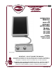
Built-In Ceramic Hotplate Operation Manual Model HC-1006, HC-1256, HC-2256
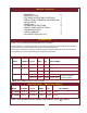
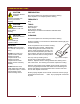
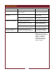
MODEL ELEMENT VOLTS AMPS kW FIELD WIRING
HC-1006 Single 7” 120 V 1ø 11.7 A 1.4 kW 14 ga. 75ºC
HC-1256 Single 9” 208 V 1ø 9.0 A 1.9 kW 10 ga. 75ºC
240 V 1ø 10.4 A 2.5 kW 10 ga. 75ºC
HC-2256 Dual 9” 208 V 1ø 18.1 A 3.8 kW 10 ga. 75ºC 3ø versions available
Refer to Installation
240 V 1ø 20.8 A 5.0 kW 10 ga. 75ºC Guide for details
NOTE: See installation guide for cutout dimensions
SPECIFICATIONS
WARRANTY xi
SPECIFICATIONS 1
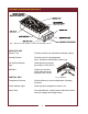
FEATURES & OPERATING CONTROLS 2
PRECAUTIONS & GENERAL INFORMATION 3
INSTALLATION 4
OPERATION 5
CLEANING INSTRUCTIONS 6
SPECIAL CARE INSTRUCTIONS 7
TROUBLESHOOTING 8
PARTS & SERVICE 9
CUSTOMER SERVICE DATA 9
Thank You for purchasing this Wells Manufacturing Co. appliance.
Proper installation, professional operation and consistent maintenance of this equipment will ensure that
it gives you the very best performance and a long, economical service life.
This manual contains the information needed to properly install this equipment, and to use and care for
the equipment in a manner which will ensure its optimum performance.
TABLE OF CONTENTS
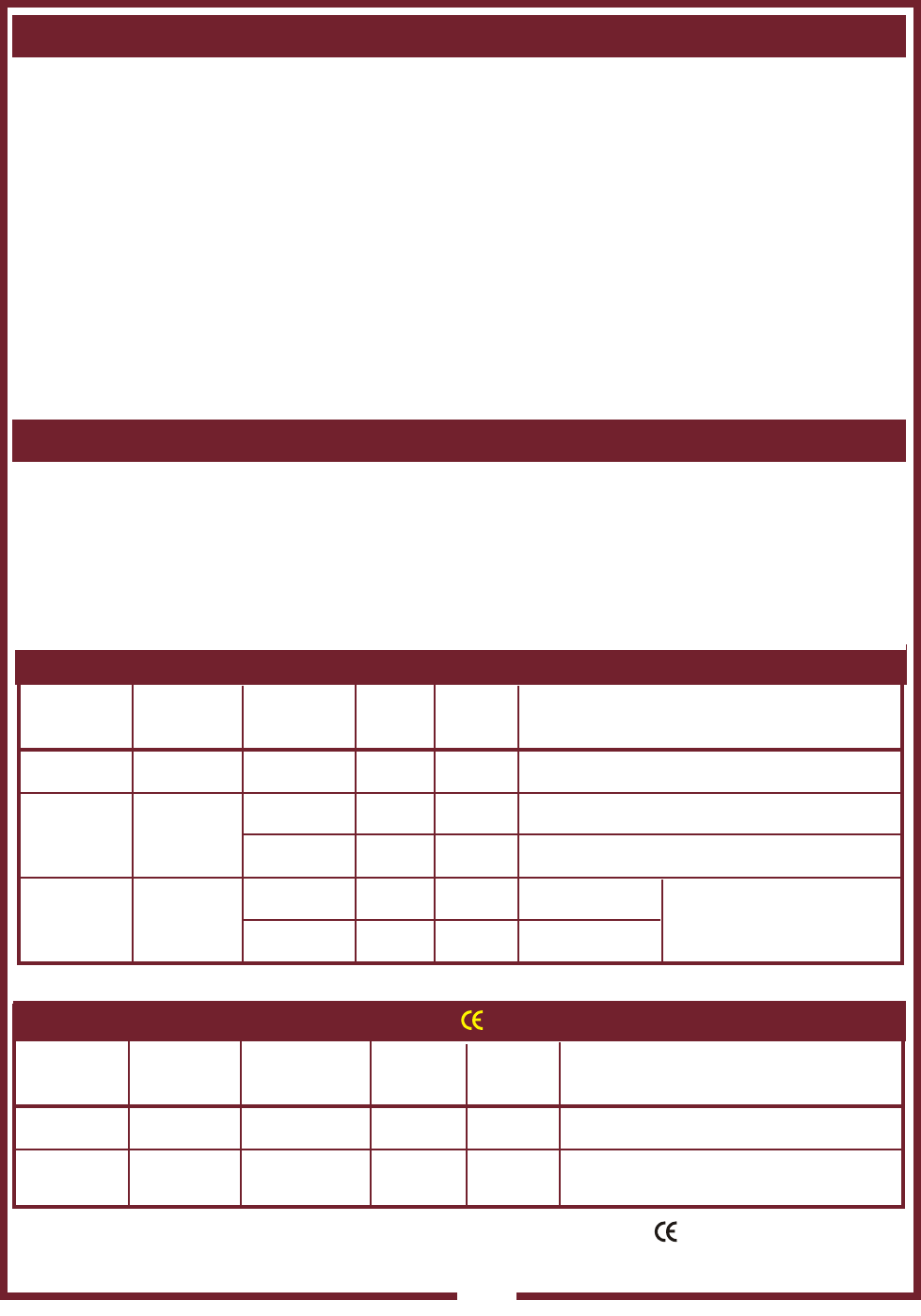
MODEL ELEMENT VOLTS AMPS kW FIELD WIRING
HC-1256EU Single 9” 220-240V 1ø 10.4 A 2.5 kW 1.5 mm
2
HC-2256EU Dual 9” 220-240V 1ø 20.8 A 5.0 kW 2.5 mm
2
Refer to the Export Manual for this equipment (p/n 301399 )for specific information.
SPECIFICATIONS — EXPORT MODELS
INTRODUCTION
1