
User manual

Well SEC Electronic Co., Ltd Http://www.wellsecurityalarm.com
Page 32 of 35 Ver 2.1
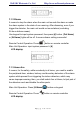
5) Connect L and N is means 0, and connect H and N is means 1,
connect neither L and N nor H and N is means 2 ;
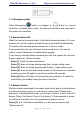
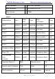
6) According to below table, select the Zone and set the 3X4 PIN
Wireless data bits code area according to selected zone.
7) Make sure the jumpers are correct. Then install the cover carefully.
8) Turn off the sensors’ power before setting .
9) Trigger the wireless sensor and test the setting result. If the wireless
sensors do not work, please check the jumpers again.
10) You can set many sensors in the same zone.
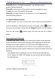
Example: If the Control Unit ID is 02102101 at the label (that is to say, the
A0-A7 is 10120120), and you want to set all wireless PIR sensor in the
zone 3(the D0-D3 is 0101), then you can set the jumper like below:
11. Technical specifications of Control Unit
Power requirements: DC 12V
Operating temperature: –20
c
0
to
c
0
60
Humidity: 20 % to 95%
Dimension: 180 x 130 x 32 mm
GSM network frequency: 900/1800/1900 MHz
Work Frequency: 315MHz±0.5MHz or 433±0.5MHz
12. Important information
12.1 Please read the User Manual carefully before you install the
Control Unit and set the Control Unit.
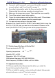
12.2 Do not install the system in close vicinity with objects that generate
strong interference, such as TV set and computer.