
Operation Manual
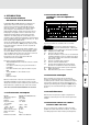
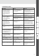


B. ONDERDELENTEKENING / SPARE PARTS LIST
ERSATZTEILZEICHNUNG / SCHÉMA DES PIÈCES
Pos. Description Quantity
1 cover 1
2 Swich (Red) 1
3 Rear panel 1
4 Solenoid Valve 1
5 Fan fixing cover 1
6 Fan 1
7 Power plug 1
8 Fan mounting plate 1
9 Gas hose (black) 0.49
10 Base plate 1
11 Foot 4
12 Holder 2
13 Heat sink 1
14 Rectifier bridge 1
15 Rectifier positioning cap 1
16 Thermoswitch 1
(normally open)
17 IGBT module 4
18 Control PCB 1
19 Collets 4
20 Heat sink 1
21 Isolating pillar 4
22 Current transformer 1
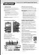
Pos. Description Quantity
23 Main transformer 1
24 Front panel PCB 1
25 Front panel 1
26 Front closure plate 1
27 Hall current sensor 1
28 Knob 1
29 Socket 2
30 Gas connector 1
31 Aero socket 1
32 Inductance 1
33 Insulation paper 1
34 Fast recovery diode 6
35 Collets 6
36 Thermoswitch 1
(normally open)
37 Holder 2
38 HF PCB 1
39 HF PCB mounting box 1
40 MUR heat sink 1
41 Heat sink 1
42 Main PCB 1
43 Three phase absorb PCB 1
45
engdeufra ned