
Product Manual
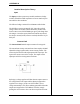
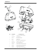
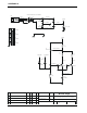
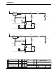
Table Of Contents

10 WELCH ALLYN UNIVERSAL DESK CHARGER SERVICE MANUAL 711380 REV. D
In the actual circuit, there is another resistor between The Output
and Adj. This is necessary for proper operation of the voltage
limit circuit, which will be discussed below. However, it should
be noted here that this resistor will have essentially no effect on
the operation of the basic current limit circuitry as described,
since the current out of the Adj pin is very low.
Transformer Headroom - The maximum trip point
(shutdown voltage) of the Simba handle is 5.06V. The current
limit circuit requires a maximum of 1.3V (across the sense
resistor) + the LM317 dropout voltage (1.6V @ 200 mA). This
requires 7.36V DC to guarantee 200 mA operation. Depending
upon the performance of the transformer, charging may take a
bit longer at low line. The low line tests have determined that the
charger will perform to nominal charge down to 100V input.
At 90V, a single handle will charge at its full rate, while two
handles will charge at about 45 mA each .
Voltage Limit
The Voltage Limit limits the output voltage to <8.78V. The
requirement is 9.5V in order to keep from biasing the input
protection Zener diode in the Simba Handle.
On its own, the simplified current limit circuit described above will
provide constant current from short circuit until the LM317 runs
out of headroom. This is great for charging the NiCad’s. How-
ever, the Simba handle eventually shuts down its charge when the
battery is fully charged. There is a 10V 1/2W input protection
Zener diode on the Simba handle, designed to protect the internal
circuitry from over voltage at the end of charge.
As mentioned in the discussion of the current limit circuit, the
LM317 adjustable regulator will shut down the output current as
the voltage between the output and the adjust pin approaches
1.25V. The voltage limit circuitry employs a 6.8V Zener diode
connected to the adjust pin on the LM317. This Zener limits the
adjust pin to 6.8V , which in turn prevents the output from nomi-
nally exceeding 6.8V +1.25V. As mentioned in the discussion of
the current limit circuit, there is a resistor between the adjust pin
and the current limit output. This limits the current through the
Zener diode when the circuit is in Voltage limit mode.
APPENDIX A