Welch Allyn® 1500 Patient Monitor Directions for use Software version 1.4.
ii Welch Allyn 1500 Patient Monitor © 2013 Welch Allyn. All rights are reserved. To support the intended use of the product described in this publication, the purchaser of the product is permitted to copy this publication, for internal distribution only, from the media provided by Welch Allyn. No other use, reproduction, or distribution of this publication, or any part of it, is permitted without written permission from Welch Allyn.
Directions for use Contents iii Contents 1 - Safety . . . . . . . . . . . . . . . . . . . . . . . . . . . . . . . . . . . . . . . . . . . . . . . . . . 1 User responsibility . . . . . . . . . . . . . . . . . . . . . . . . . . . . . . . . . . . . . . . . . . . . . . . . 1 Intended use. . . . . . . . . . . . . . . . . . . . . . . . . . . . . . . . . . . . . . . . . . . . . . . . . . . . . 1 Organizational measures . . . . . . . . . . . . . . . . . . . . . . . . . . . . . . . . . . . . . . . . . . .
iv Contents Welch Allyn 1500 patient monitor 6 - Acuity Central Station . . . . . . . . . . . . . . . . . . . . . . . . . . . . . . . . . . . 91 Safety . . . . . . . . . . . . . . . . . . . . . . . . . . . . . . . . . . . . . . . . . . . . . . . . . . . . . . . . . Introduction. . . . . . . . . . . . . . . . . . . . . . . . . . . . . . . . . . . . . . . . . . . . . . . . . . . . . Connect to the Acuity Central Station . . . . . . . . . . . . . . . . . . . . . . . . . . . . . . . . Working with Acuity . .
1 1 Safety User responsibility • The numerical and graphical results and any interpretation given must be examined with respect to the overall clinical condition of the patient and the general recorded data quality. • The indications given by this equipment are not a substitute for regular checking of vital functions. • This monitor is only to be used by those trained in its operation or repair.
2 Safety Welch Allyn 1500 Patient Monitor Organizational measures • Before using the monitor, ensure that an introduction regarding the monitor functions and the safety precautions have been provided by a medical product representative. • Observe the operating instructions and maintenance instructions. • These operating instructions do not override any statutory or local regulations, or procedures for the prevention of accidents and environmental protection.
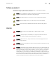
Directions for use Safety 3 Safety equipment Operating the monitor without the correctly rated fuse, or with defective cables, constitutes a danger to patient safety. Therefore: Caution Do not operate the monitor if the ground connection is suspect or if the mains lead is damaged or suspected of being damaged. Caution Damaged cables and connections must immediately be replaced. Caution Electrical safety devices, such as fuses, must not be modified.
4 Safety Welch Allyn 1500 Patient Monitor Operation with other devices Caution Do not use the monitor in or near an MRI suite. • Only use accessories and other parts recommended or supplied by Welch Allyn. Use of other than recommended or supplied parts may result in injury, inaccurate information or damage to the monitor. • Accessory equipment connected to the analogue and digital interfaces must be certified according to the respective IEC standards (e.g.
Directions for use Safety 5 Maintenance WARNING Danger of electric shock. Do not open the monitor case. There are no user serviceable parts inside. Servicing may only be performed by a qualified technician authorized by Welch Allyn. WARNING Before cleaning and to isolate the mains power supply, switch the monitor off and disconnect it from the mains by removing the plug. Caution Do not use high temperature sterilization processes (such as autoclaving). Do not use E-beam or gamma radiation sterilization.
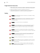
6 Safety Welch Allyn 1500 Patient Monitor The following symbols appear on the monitor, or accessories. Symbol Definition Potential equalization (earth ground) Symbol © Definition CF symbol. This monitor is classified safe for internal and external use. However, it is only defibrillation protected when used with the original Welch Allyn patient cable! The monitor can be recycled. Recycle the monitor and battery separately from other waste. Refer to www.welchallyn.
Directions for use Safety 7 Additional terms Implied authorization Possession or purchase of this monitor does not convey any express or implied license to use the monitor with replacement parts which would alone, or in combination with this monitor, fall within the scope of one or more patents relating to this monitor. Terms of warranty Your monitor is warranted against defects in material and manufacture for the duration of one year (from date of purchase).
8 Safety Welch Allyn 1500 Patient Monitor
9 2 Introduction The monitor is designed for adult, pediatric and neonatal use. It has a 15-inch screen for comprehensive vital data monitoring. The monitor can be used with mains power (100 – 240 VAC) or with an internal battery.
10 Introduction Welch Allyn 1500 Patient Monitor The Welch Allyn® 1500 Patient Monitor Front panel Visual alarm indicator Patient connection panel Function button panel Trim knob Back panel Ethernet (RJ45) connector Potential equalization (ground) Nurse call connector* Mains connector (100-240 VAC) and fuse panel Printer USB connector (lift door) *The nurse call can be used to give an external indication of a parameter alarm.
Directions for use Introduction Connection panel Temperature 1 Cardiac Output Temperature 2 etCO2 sampling input SVC (service only) etCO2 sampling exhaust ECG NIBP SpO2 IBP 4 IBP 1 IBP 3 IBP 2 Note The connection panel layout will vary according to the options installed.
12 Introduction Welch Allyn 1500 Patient Monitor Function buttons Print Printout of three waveforms and all parameters. The waveforms and print settings are defined in the printer menu (see “Recorder” on page 113). Note that an auto printout can also be obtained when a limit is violated. This is also defined in system setup. Alarm silence Silence / resume an audible alarm, or confirmation of displayed messages. The silence time is defined in the Setup/Administrator menu (see “Administrator” on page 118).
Directions for use Introduction 13 Setup menu overview Press Note to enter the setup menu and adjust the following settings and options: The following is an overview of the setup menu options. Further details are given in section 8 (see “Settings” on page 111). Parameter Settings/Submenus Alarm Suspend Silences all alarms for a set period. The silence time is defined in the Administrator menu (alarms). Arrhythmia1 Arrhythmia limits and alarm levels. Pacer Display and analysis (on/off).
14 Introduction Welch Allyn 1500 Patient Monitor Parameter Settings/Submenus Administrator Configuration Display of monitor ID, network settings, options, etc. This is for information only. Alarms Alarm settings - silence time, suspend time, etc. This requires a password to enter (see “Settings” on page 111). System Time and date settings and unit preference (cm/in, kg/lb).
Directions for use Introduction 15 Display overview Waveform fields Time of last blood pressure measurement Parameter fields Alarm and system messages Blood pressure Temperature Information field See“Information field” following Note The waveform display is changed in setup menu (see “Defining display waveforms” on page 27). Note The parameter fields can be changed according to licensed options, parameter selection (see“Defining parameter fields” on page 25), and patient panel options.
16 Introduction Welch Allyn 1500 Patient Monitor Information field Top line a b c The left box on the top line (a) displays the patient’s room number (entered in the patient information screen). If the monitor is connected to the Acuity Central Station, the room number is taken from Acuity. The middle box (b) displays the patient mode (Neonatal, Pediatric, or Adult) indicated by the highlighted icon. The right box (c) indicates the monitor’s network connection: Connected to Acuity Central Station.
17 3 Operation Startup and initial preparation WARNING Danger of electrical shock. Do not operate the monitor if the ground connection is suspect or if the mains lead is damaged or suspected of being damaged. WARNING Network the monitor to an Acuity Central Station only. Connecting to other networks could damage the monitor or injure the patient. If in doubt about the network jacks or devices, consult your facility’s Biomedical Engineering Department. Connections a 1.
18 Operation Welch Allyn 1500 Patient Monitor Inserting recorder paper Note The monitor is delivered without printing paper installed. Only use original Welch Allyn printing paper. The thermal paper is sensitive to heat, humidity, and chemical vapors. Store the paper in a cool, dry and chemical free area. b c a 1. Pull the locking catch (a) to the front. The paper tray is unlocked. 2. Pull the paper tray out. 3. Insert paper and pull the beginning of the paper out.
Directions for use Operation Switching the monitor on or off Switching the monitor on To turn the monitor on, press the On/Off button . Switching the monitor off To turn the monitor off, press the On/Off button for approximately 4 seconds. The following message is displayed when the monitor is shutting down. Initial Power up 1. Press the On/Off button (confirmed by a beep). 2. Confirm the New Patient dialogue with Yes or No. • Yes: Previous patient information is deleted.
20 Operation Welch Allyn 1500 Patient Monitor Initial settings Caution Only authorized personnel, trained in the operation of this monitor, are qualified to do the setups in the following menu. Alarm and general settings are given in the setup menu. Initial monitor settings may include general alarm settings (alarm silence time, alarm delay time, etc.), and general monitor settings (height and weight units, time and date, etc.). Access the setup as follows: 1. Press the Setup button . 2.
Directions for use Operation 21 Saving the user-defined settings as default All monitor settings, including alarms settings, are stored until the monitor is switched off. To save the user defined settings as default, 1. Press the Setup button . 2. Select Administrator > System > Save User Defaults. Note The system menu is password protected. The password is 49, 48, 46. 3. Confirm with ok: Restoring the user settings 1. Press the Setup button . 2. Select Restore User Defaults.
22 Operation Welch Allyn 1500 Patient Monitor Power supply Mains connected When the mains supply is connected, the mains LED is illuminated (a). When the mains supply is connected, and the battery is recharging both mains LED (a) and the battery LED (b) are illuminated. For battery recharging see “Recharging the battery” on page 101. a b Mains interrupted Note If the mains supply is interrupted, the monitor automatically switches over to battery operation. The user settings are maintained.
Directions for use Operation 23 Battery operation Two batteries are available for the monitor: • Lithium-Ion battery: This type of battery will provide power for approximately two hours when fully charged. • Lead acid battery: This type of battery will provide power for approximately one hour when fully charged. When running on battery power the battery symbol is displayed next to the time. The battery indicator gives an approximate guide to the capacity of the battery: • Full = between 87.
24 Operation Welch Allyn 1500 Patient Monitor Standby mode WARNING In standby mode, vital signs data and alarms are no longer displayed or collected. In standby mode, patient monitoring is temporarily interrupted. Confirmed patient information is saved. Note 1. Patient information that has not been confirmed is lost when standby mode is entered. Press the Standby button Note . The following screen is displayed: The standby message is continuously displayed while the unit is in standby mode. 2.
Directions for use Operation 25 Defining parameter fields 1. Press the Setup button . 2. Select Parameters. The screen will vary according to the licensed options: • etCO2, ST and CO are only displayed when the options are licensed. • The Masimo settings enabled (yes / no), gives extra settings for SpO2 measurement (see “SpO2 monitoring” on page 68) and is only displayed when the Masimo module is installed.
26 Operation Welch Allyn 1500 Patient Monitor Parameter field display RR or when enabled, etCO2, measurement, ST measurement, or both ST and etCO2 measurements. Two or four IBP measurements (or this area is left blank when no IBP measurement are selected). Cardiac Output measurement (when enabled). T1, T1 and T2, or T1 and ΔT • When etCO2 is enabled, the CO2 parameter replaces the RR parameter below the heart rate.
Directions for use Operation 27 Defining display waveforms 1. Press the Setup button . 2. Select Waveform Area. 3. The waveforms are configured through the pull-down menus. 4. Set the amplitude for each waveform according to preference and signal strength. Set the sweep speed (for all waveforms) according to preference and patient. Note The RESP and SpO2 sweep speed values are not configurable. 5. Select OK to save.
28 Operation Welch Allyn 1500 Patient Monitor Waveform display The waveforms that can be configured are as follows: Waveform position ECG RESP CO2 Trend ST • SpO2 1 • 2 • • • • 3 • • • • • 4 • • • 5 6 P1 P2 P3 P4 • • • • 7 • • 8 • • • RESP in waveform 2 can only be displayed when etCO2 is not enabled. • When ST is enabled SpO2 is available for waveform 4 only. When ST is not enabled SpO2 is available for waveform 3 only.
Directions for use Operation 29 Trend data The monitor records up to 24 hours of trend data at one-minute intervals. The trend values are displayed at the user defined interval (see below) and additionally after every manual NIBP measurement. • Trend data is deleted when a new patient is entered. • When the memory is full, the oldest trend data is overwritten. • The display interval for the trend table can selected for intervals of one minute, five minutes, 15 minutes, one hour, or four hours.
30 Operation Welch Allyn 1500 Patient Monitor Displaying trend data in the measurements screen The HR trend can also be displayed in the waveforms: Press the Setup button . and select Waveforms. Scroll down for more options.
Directions for use Operation 31 Settings via a parameter field 1. Select the desired parameter measurement field using the trim knob. A white frame appears around the selected field. 2. Press the trim knob to display the menu. The following example is displayed when the heart rate settings screen is selected. Other setting screens are similar: 3. The settings can be saved as default (see “Saving the user-defined settings as default” on page 21).
32 Operation Welch Allyn 1500 Patient Monitor
33 4 Alarms Display of alarms During initial powerup No alarms are displayed if no patient is being monitored. During monitoring There are three alarm priorities: Alarm type Priority LED visual alarm indicator Audible signal Display Technical Low Blue Single deep tone every 2 seconds Text display in the alarm status field at the bottom. Parameter Medium Yellow (flashes with parameter field) Two tone high/low Text display in the alarm status field at the every second. bottom.
34 Alarms Welch Allyn 1500 Patient Monitor Silencing an alarm Acknowledging an alarm Alarm Limit Press the Alarm button to silence the alarm. The audible alarm is silenced for 1, 1.5 or 2 minutes. The visual parameter alarm continues to be displayed. Press the Alarm button again to resume the alarm. After the defined silence time, the audible alarm is reactivated. The silence time is defined in Setup > Setup Administrator> Alarms > Alarm Silence Time (see “Administrator” on page 118).
Directions for use Alarms 35 Switching off all alarms This function allows all audible alarms to be muted for an unlimited time during surgical and clinical interactions while simultaneously monitoring the patient and recording the parameters and alarm status. During this time the visual alarms continue to be displayed and the Audio Off symbol s displayed on the monitor. To switch off all alarms, proceed as follows: 1. Press the Setup button . 2.
36 Alarms Welch Allyn 1500 Patient Monitor Switching off an individual parameter alarm WARNING The audible alarm is silenced permanently. The settings are not reset. Physiological alarms of the patient are silenced. Use this function only if disconnecting a sensor from the patient for a long period of time. 1.
Directions for use Alarms 37 Alarm limit setting Note 1. All alarm limits are reset to the default settings after confirming a new patient (see “Standby mode” on page 24), or switching off the monitor. Press the Setup button . 2. Select the menu item Alarms. 3. Use the trim knob to scroll through the alarm settings and select the limits. Note Individual parameter alarm limits can be set in the parameter menu (see “Monitoring and Measurements” on page 39).
38 Alarms Welch Allyn 1500 Patient Monitor Physiological alarms Alarm abbreviation Description Priority SpO2 low/high Oxygen saturation of the blood Medium PP low/high Peripheral pulse of SpO2 Medium RRECG low/high Respiration rate impedance Medium Apnea limit Apnea time limit exceeded Medium CO2 low/high Inspiratory CO2 Medium RRCO2 low/high Capnographic respiration rate Medium etCO2 low/high End-tidal expiratory CO2 Medium NIBPs low/high Systolic blood pressure Medium NIBPm l
39 5 Monitoring and Measurements Caution The guidelines in this section are given as an overview only. They are not a substitute for, nor do they overrule manufacturer documentation and instructions or departmental procedures. Note Values are only displayed when the ECG cable or at least one sensor is connected. If a sensor is disconnected, a technical alarm is issued. The measured value will no longer be displayed if the sensor is disconnected and the alarm is acknowledged.
40 Monitoring and Measurements Welch Allyn 1500 Patient Monitor ECG WARNING In order to minimize interference and the danger of burns to the patient, only use Welch Allyn ECG cables. Keep the ECG cable as far away as possible from any electrosurgical cables. Make sure that the electrosurgical return conductor (neutral) is properly attached to the patient and that good contact is made.
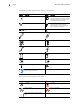
Directions for use 3-lead 5-lead Monitoring and Measurements 41
42 Monitoring and Measurements Welch Allyn 1500 Patient Monitor 12-lead Note This graphic shows the IEC color configuration. The AHA (U.S.) color configuration is shown in “Electrode identification and color code IEC/AHA” on page 43.
Directions for use Monitoring and Measurements 43 Electrode identification and color code IEC/AHA The electrode placements shown in this manual are labelled with the colors according to IEC requirements. The equivalent AHA colors are given below. IEC (Europe) AHA (U.S.
44 Monitoring and Measurements Welch Allyn 1500 Patient Monitor Pacemaker monitoring WARNING Patients with a pacemaker must be observed continuously because the heart rate from the pacemaker might still be registered in case of a cardiac arrest or some arrhythmias. See specification “Technical data” on page 127 for disclosure of the pacemaker pulse rejection capability of this monitor. WARNING Pacemaker monitoring is not possible with ECG cables that have unshielded lead wires.
Directions for use Monitoring and Measurements 45 Activating the pacer display 1. Select the HR measurement field using the trim knob. A white frame appears around the measurement field. 2. Press the trim knob to display the menu. 3. Scroll down to the pacer display option and select yes. Pacemaker spikes are presented as vertical lines (a) on the ECG trace. These vertical lines represent neither magnitude nor duration of the pacemaker pulse but are purely time relative.
46 Monitoring and Measurements Welch Allyn 1500 Patient Monitor ECG display ECG traces can be displayed in waveforms 1, 2 and 3. The waveform lead and size is defined in the waveform display menu (see “Settings via a parameter field” on page 31). 1. Press the Setup button 2. Select Waveforms. .
Directions for use Monitoring and Measurements 47 12-lead resting ECG (option) With this option it is possible to record a 12-lead resting ECG. One resting ECG can be stored at a time. The resting ECG cannot be viewed on the monitor but can be printed on the internal printer. Note The 12-lead resting ECG is an option and only appears in the setup menu when enabled. Taking a resting ECG 1. Press the Setup button . 2. Select 12-lead ECG. 3. Check electrode status.
48 Monitoring and Measurements Welch Allyn 1500 Patient Monitor ECG menu settings Note The parameter settings are selected with the trim knob. (See “Settings via a parameter field” on page 31). The default settings are in bold. Main menu Parameter Description Setup HR ECG Lead Lead selection I, II, III, V, AVL, AVR, AVF Size 0.5, 1, 2, 4 mV/cm HR/PR source1 HR/PR Tone 1 ECG Filter 1. 2. 3.
Directions for use Monitoring and Measurements 49 ECG alarms and messages Message Possible cause Suggested action HR – asystole/ASY No QRS detected for 4 seconds. Check the patient. ECG signal lower than 0.5 mV. HR – ventricular fibrillation/VF No organized ventricular rhythm Check the patient. detected. ECG signal lower than 0.5 mV. HR – artifact Patient has moved. Calm the patient. Bad electrode. Checking the electrode pads. Interferences by other devices.
50 Monitoring and Measurements Welch Allyn 1500 Patient Monitor Arrhythmia Arrhythmia settings Note The full arrhythmia menu is only displayed when the full arrhythmia option is licensed. When the full arrhythmia option has not been enabled, settings are made for VFib, Asystol and Vtach only. Note The arrhythmia menu is not available when the monitor is connected to Acuity. 1. Press the Setup button . 2. Select Arrhythmia. The default settings are in bold.
Directions for use Monitoring and Measurements 51 Main menu Parameter Description Setup Arrhythmia (continued) Trigeminy Alarm Level (High, Medium, Low, Off), Print on alarm Yes/No. Tachycardia Tachycardia 150 to 250 (180) Alarm Level (High, Medium, Low, Off), Print on alarm Yes/No. Bradycardia Bradycardia 20 to 100 (45) Alarm Level (High, Medium, Low, Off), Print on alarm Yes/No. Pause Alarm Level (High, Medium, Low, Off), Print on alarm Yes/No.
52 Monitoring and Measurements Welch Allyn 1500 Patient Monitor ST measurement (option) The ST segment represents the period from the end of ventricular depolarization to the beginning of ventricular repolarization. The ST segment lies between the end of the QRS complex and the initial deflection of the T-wave. It is normally isoelectric. ST Analysis is a useful diagnostic tool because it may provide an early indication of myocardial ischemia or infarction.
Directions for use Monitoring and Measurements 53 ST settings Note ST measurements can only be displayed when the full arrhythmia and ST option is licensed, and when ST is enabled in setup parameters (See “Defining parameter fields” on page 25). Note When the monitor is connected to the Acuity Central Station, ST support is provided by Acuity and the ST option is not displayed on the monitor.
54 Monitoring and Measurements Welch Allyn 1500 Patient Monitor ST alarm messages Alarm Possible cause Suggested action ST > [upper limit] ST< [lower limit] ST is higher or lower than the alarm limit. Check the patient.
Directions for use Monitoring and Measurements 55 Respiration rate Note The RR measurement field is not displayed if the etCO2 field is enabled. If the RR should be measured via the ECG instead of etCO2, the etCO2 measurement field must be deactivated as follows: Press the Setup button Note , select Parameters and deactivate etCO2 (No). The RR signal is measured via the R (RA) and F (LL) electrodes of the ECG cable (impedance measurement).
56 Monitoring and Measurements Welch Allyn 1500 Patient Monitor Respiration rate alarms and messages Message Possible cause Suggested action RR out of range (too high) The patient's RR is too high for accurate measurement. Check the patient. Electrical interferences from other devices. Remove source of the interference. Signal disturbed due to frequent Check and reapply/replace electrodes if artifacts caused by bad required. electrode contact. RR lead off Electrode loose/defective.
Directions for use Monitoring and Measurements 57 Capnography The capnography module is intended to provide professionally trained health care providers with continuous, non-invasive measurement and monitoring of carbon dioxide concentration of the expired and inspired breath and respiration rate. It is intended for use with neonatal, pediatric, and adult patients. Note The etCO2 menu is only displayed when the etCO2 option is enabled.
58 Monitoring and Measurements Welch Allyn 1500 Patient Monitor WARNING If too much moisture enters the sampling line (i.e., from ambient humidity or breathing of unusually humid air), and the sampling line cannot be cleared, the message Blockage appears in the message area. Replace the sampling line once the sampling line blockage message appears. Caution In high-altitude environments, etCO2 values may be lower than values observed at sea level.
Directions for use Monitoring and Measurements 59 Preparing the Oridion sensor Basic principles for choosing microstream CO2 sampling lines When choosing Microstream CO2 sampling lines, the following should be considered: • The condition of the patient (ventilated or not ventilated) • If the patient is ventilated, whether ventilation is humidified or non-humidified • Patient’s size and weight • The probability that the patient will switch between oral and nasal breathing • Duration of use • Fo
60 Monitoring and Measurements Welch Allyn 1500 Patient Monitor etCO2 settings The parameter settings are selected with the trim knob, described previously (see “Settings via a parameter field” on page 31). The default settings are in bold. Parameter Description Size 0 to 40 mmHg, 0 to 60mmHg, 0 to 80mmHg. Units mmHg/kPa. Apnea time 6, 10, 15, 20, 25, 30 seconds. EtCO2 lower /upper limit Range: 0- 99 mmHg Lower limit default 25 mmHg / 3 kPa) Upper limit default 60 mmHg / 8 kPa.
Directions for use Monitoring and Measurements 61 Integrated Pulmonary Index (IPI) settings and measurement The capnography module provides the clinician with an integrated pulmonary index (IPI). The IPI is based on end tidal carbon dioxide, respiration rate, oxygen saturation and heart rate. The IPI is a single index of an adult or pediatric patient's ventilatory status displayed on a scale of 1 - 10, where 10 indicates optimal pulmonary status.
62 Monitoring and Measurements Welch Allyn 1500 Patient Monitor Assessing the IPI value IPI can provide an early indication of a change in ventilatory status which may not be shown by the current value of any of the four parameters individually. The IPI is designed to summarize information regarding patient status, possibly before etCO2, RR, SpO2, or PR values reach levels of clinical concern.
Directions for use Monitoring and Measurements etCO2 alarms and messages l Message Possible cause Suggested action etCO2 > [upper limit] etCO2 < [lower limit] etCO2 is higher / lower than alarm limit. Check the patient. RR > [upper limit] RR < [lower limit] RR is higher / lower than alarm limit. Check the patient. FiCO2 > [upper limit] FiCO2 has exceeded alarm limit. Check the patient and ventilator.
64 Monitoring and Measurements Welch Allyn 1500 Patient Monitor NIBP monitoring Safety WARNING To prevent extensive pressure on the extremity, it is very important to: • • Choose the correct cuff size. Check the initial pressure in the NIBP menu. The correct initial pressure for adults is 160 mmHg, for pediatric patients 120 mmHg, and for neonates 90 mmHg.
Directions for use Monitoring and Measurements Taking a single NIBP measurement 1. Press the NIBP start/stop button . 2. The measurement can be stopped at any time by pressing the button again. Automatic blood pressure measurement 1. Press the NIBP measurement interval button . 2. Select the interval between 3 minutes and 60 minutes, and confirm your selection with OK. 3. The message NIBP interval – xx minutes is displayed. 4.
66 Monitoring and Measurements Welch Allyn 1500 Patient Monitor NIBP settings The parameter settings are selected with the trim knob, described previously (see “Settings via a parameter field” on page 31). The default settings are in bold. Parameter Description NIBP Interval Off, 3, 5, 10, 15, 30, 60 Format Sys/Dia or Mean. This defines the main measurement to be displayed, that is the larger measurement displayed in the NIBP box.
Directions for use Monitoring and Measurements 67 NIBP alarms and messages Message Possible cause Suggested action NIBP needs service No NIBP module detected. Switch off and restart. Replace monitor. NIBP artifact cannot measure Patient has moved. Cannot measure NIBP Patient has moved. Check and calm patient. Very unsteady pulse. Apply cuff to another extremity with less movement and steady pulse. Air tube plugged or leaking. Check tube and cuff.
68 Monitoring and Measurements Welch Allyn 1500 Patient Monitor SpO2 monitoring Two SpO2 modules are available with the monitor - Masimo or Nellcor. The two modules are distinguished by the connectors. The display data and waveform are similar for both modules. The Masimo module has extra clinical settings for signal processing (see “Masimo settings” on page 71).
Directions for use Monitoring and Measurements 69 Safety WARNING Only use sensors recommended from Welch Allyn for SpO2 measurement with the monitor. Only use Masimo sensors when the monitor has a Masimo module. Only use Nellcor sensors when the monitor has a Nellcor module. Other sensors can impact the performance and give incorrect measurement readings. WARNING The information in this manual does not overrule any instructions given in the SpO2 sensor directions for use.
70 Monitoring and Measurements Welch Allyn 1500 Patient Monitor SpO2 settings The parameter settings are selected with the trim knob, described previously (see “Settings via a parameter field” on page 31). The default settings are in bold. Parameter Description SpO2 alarm pause When the alarm is paused the message SpO2 Alarms Paused appears in the message line. The alarm is paused until the sensor is reinstalled. HR/PR source1 ECG, SpO2, P1 (selection of the heart rate source).
Directions for use Monitoring and Measurements 71 Masimo settings When the monitor has a Masimo module installed, the following settings are additionally available: Note The extra settings for masimo modules are only available when Masimo settings enabled in the parameter settings (see “Defining parameter fields” on page 25). Parameter Description Display Signal IQ (SIQ) Waveform 1 On, Off. This value shows the acquired signal quality and timing of the pulse relative to the plethysmograph.
72 Monitoring and Measurements Welch Allyn 1500 Patient Monitor SpO2 messages Message Possible cause SpO2 – check sensor Defective SpO2 sensor Suggested action Replace the sensor. Incorrect settings in the monitor Check the monitor settings. SpO2 – check sensor Poor sensor contact or the placement sensor has fallen off Check the contact between the sensor and the patient. Sensor is disturbed by ambient light Cover the sensor.
Directions for use Monitoring and Measurements 73 IBP monitoring Safety WARNING Carefully read the manufacturer's instructions before using the invasive blood pressure kit. WARNING When applying the kit to the patient, make sure that absolutely no air penetrates the system. WARNING To achieve correct arterial pressure measurement, the pressure sensor must be installed on the level of the right atrium. WARNING If the pressure sensor's position is moved after calibration, this may give inaccurate values.
74 Monitoring and Measurements Welch Allyn 1500 Patient Monitor Preparing IBP measurement Refer to the manufacturer’s directions for use for operating information for the IBP sensor. IBP settings The parameter settings are selected with the trim knob, described previously (see “Settings via a parameter field” on page 31). Note When changing the IBP label in the setup window, the upper and lower alarm limits will change to match the label (see“IBP alarm defaults” on page 75).
Directions for use Monitoring and Measurements IBP alarm defaults Label / Parameter P1, P2, P3, P4 SYS P1, P2, P3, P4 DIA P1, P2, P3, P4 Mean ART SYS ART DIA ART Mean CVP SYS CVP DIA CVP Mean PA SYS PA DIA PA Mean ICP SYS ICP DIA ICP Mean RA SYS RA DIA RA Mean LA SYS LA DIA LA Mean UA SYS UA DIA UA Mean UV SYS UV DIA UV Mean Adult Lower Limit 6 -4 0 75 35 50 6 -4 0 10 0 0 6 -4 0 6 -4 0 6 -4 0 Adult Upper Limit 14 6 10 220 110 120 14 6 10 34 16 20 14 6 10 14 6 10 14 6 10 Pediatric Lower Limit 2 -4 0 75
76 Monitoring and Measurements Welch Allyn 1500 Patient Monitor IBP zero set • Zero Set must be carried out before every application. • To prevent incorrect measurement readings due to the sensor's physical null drift, calibrate the sensor every 24 hours. Note 1. Ensure the sensor is kept still during zero set. If the pressure sensor's position is moved during zero set, this can lead to incorrect values. Move to the desired IBP measurement field (P1, P2) using the trim knob. 2.
Directions for use Monitoring and Measurements 77 Temperature monitoring • Depending on the sensor type, the sensor can be applied to the ear, the skin or the rectum. • To achieve a reliable measured value, independent of the measuring site, the measurement duration must be at least 2 minutes. Temperature settings The parameter settings are selected with the trim knob, described previously (see “Settings via a parameter field” on page 31). The default settings are in bold.
78 Monitoring and Measurements Welch Allyn 1500 Patient Monitor Cardiac output (option) Introduction The WA 1500 patient monitor uses the thermodilution method of measuring cardiac output. A pulmonary artery catheter (PAC) is inserted into the right side of the heart. The PAC is balloon tipped and is inflated to help it through the right ventricle to occlude a smaller branch of the pulmonary artery system.
Directions for use Monitoring and Measurements 79 Safety WARNING Carefully read the manufacturer's catheter instructions before carrying out measurements. WARNING When an invasive catheter is introduced into an arterial vessel, the circulation in the terminal vessels must be checked at regular intervals. WARNING When applying the kit to the patient, make sure that no air penetrates the system.
80 Monitoring and Measurements Welch Allyn 1500 Patient Monitor Approved catheters and injectate sensor type Catheters The monitor will work with any blood temperature sensor that is Edwards-compatible. Injectate Sensor The injectate sensor must be a Baxter/Edwards/Abbott "in-line" thermistor. Note The monitor does not support bath probe or arrow flow-through sensor. Preparing for cardiac output measurement Note 1. The CO is only displayed when the CO option is enabled.
Directions for use Monitoring and Measurements 81 Taking a CO measurement Cardiac output settings 1. Use the trim knob to select and highlight the CO measurement field. Press the trim knob to display the settings. Note Parameter selection with the trim knob is described previously (see “Settings via a parameter field” on page 31). 2. The settings screen appears: 3. Make the settings as shown on the following page.
82 Monitoring and Measurements Welch Allyn 1500 Patient Monitor The default settings are in bold. Parameter Description Mode Auto, manual. In auto mode the unit monitors the blood temperature and indicates that a measurement can be commenced only when the temperature is stable. In manual mode, the user monitors starts the measurement at any time. Computation constant Between 000 and 999 (starting figure 400).
Directions for use Monitoring and Measurements 83 Taking a CO measurement 1. Insert the catheter and prepare injectate solution in accordance with the instructions provided by the manufacturer. 2. On the monitor make the settings and enter the computation constant (see previous page). 3. The blood temperature is monitored and when the temperature is stable, Ready is indicated at the top of the screen.
84 Monitoring and Measurements Welch Allyn 1500 Patient Monitor 4. Inject the solution. The temperature waveform is displayed and the CO value given in measurement 1. Note Follow you facility’s guidelines for injecting the solution. 5. Repeat to obtain 3- 5 measurements.
Directions for use Monitoring and Measurements 85 Saving a measurement When three or more consistent measurements have been obtained, Save Average can be selected to save the measurement. You are prompted to confirm. When confirmed the averaged measurement is entered in the CO field at the bottom of the screen. The time when the measurement was made appears in the top right corner and the measurement parameter (CO or CI) appears in the left corner.
86 Monitoring and Measurements Welch Allyn 1500 Patient Monitor CO messages The following self-clearing alert messages may be displayed during the CO measurement process: Message Message trigger and when displayed BT out of range (too high or BT out of range (too low) Verify correct catheter position. Blood temperature out of range (High or Low), displayed when: • detected during a CO measurement session.
Directions for use Monitoring and Measurements Hemodynamic calculations 1. Press the Setup button . 2. Select Hemodynamic Calculations. Entered Values Calculated Values Enter the following parameters to calculate the hemodynamic calculations (see next page). As soon as the calculated values have sufficient data to for the entered parameters, the calculated values are shown.
88 Monitoring and Measurements Welch Allyn 1500 Patient Monitor Calculations Parameter Units Time BSA Description Time when the calculations were made m2 Body surface area in m2 calculated as follows: • SV ml Stroke volume (milliliters / stroke): • SVR dyne-sec/cm5 dyne-sec/cm5 kg-m gm-m kg-m gm-m l/min/m2 ml/m2 RVSW = SV * (PAm - CVPm) * 0.0136 Cardiac Index: • SVI LVSW = SV * (ARTm - PAWP) * 0.0136 Right Ventricular Stroke Work: • CI LVSW = SV * (ARTm - PAWP) * 0.
Directions for use Monitoring and Measurements Parameter Units Description SVRI dyne-sec/cm5/m2 Systemic Vascular Resistance Index: • PVRI dyne-sec/cm5/m2 Pulmonary Vascular Resistance Index: • LCWI kg-m/m2 gm-m/m2 kg-m/m2 gm-m/m2 LVSWI = LVSW / BSA Right Cardiac Work Index: • RVSWI LCWI = LCW / BSA Left Ventricular Stroke Work Index: • RCWI PVRI = PVR * BSA Left Cardiac Work Index: • LVSWI SVRI = SRV * BSA RCWI = RCW / BSA Right Ventricular Stroke Work Index: • RCSWI = RVSW / BS
90 Monitoring and Measurements Welch Allyn 1500 Patient Monitor
91 6 Acuity Central Station Note Acuity connectivity is a licensable feature. To order this feature contact your Welch Allyn sales representative (see page ii). The network settings are defined by the system administrator (see the Welch Allyn 1500 patient monitor service manual). Safety WARNING Connect the monitor to an Acuity system only. Connecting to other networks could damage the monitor or injure the patient.
92 Acuity Central Station Welch Allyn 1500 Patient Monitor Caution Make sure the Acuity network cable is not damaged. The Acuity network cable is the sole link between the monitor and the Acuity Central Station. Caution When the monitor is not connected to the network there are no patient alarms or alerts at the Acuity Central Station. Caution If you don’t set alarm limits, the Acuity system uses preset settings (for arrhythmia test limits), and the power up default settings for the monitor.
Directions for use Acuity Central Station 93 Introduction The Acuity Central Station provides central patient monitoring for monitoring devices connected to the network. The monitor communicates through a hardwired Acuity connection. While connected to the network, the monitor sends data to Acuity. This data is continuously analyzed to provide appropriate alarm or alert messages at the Central Station and other network devices such as a hallway message panel or the monitor itself.
94 Acuity Central Station Welch Allyn 1500 Patient Monitor Working with Acuity Please consult the Acuity directions for use for full operating instructions. Enabling the Acuity connection Note 1. Acuity can only be enabled when the option is licensed. If the Acuity option is not licensed, this menu item is not available. Press the Setup button . 2. Select Administrator > System (password required 49, 48, 46) and set Acuity Enabled (yes).
Directions for use Acuity Central Station Acuity alarm default settings Adult settings Parameter Acuity range limit Acuity lower limit (default) Acuity upper limit (default) HR 25 - 250 50 120 PR (NIBP) 25 - 250 50 120 PR (IBP) 25 - 250 50 120 PR (SpO2) 25 - 250 50 120 SpO2 SAT (%) 50 - 100 90 100 RR-ECG 2 - 150 5 30 RR-CO2 2 - 150 5 30 Apnea Delay (s) 6 - 30 N/A 15 etCO2 (mmhg) 0 - 99 25 60 0 - 13.2 3.0 8.0 2 - 25 N/A 5 inCO2 (kPa) 0.2 - 5.0 N/A 0.
96 Acuity Central Station Welch Allyn 1500 Patient Monitor Pediatric settings Parameter Acuity range limit Acuity lower limit (default) Acuity upper limit (default) HR 25 - 250 50 150 PR (NIBP) 25 - 250 50 150 PR (IBP) 25 - 250 50 150 PR (SpO2) 25 - 250 50 150 SpO2 SAT (%) 50 - 100 90 100 RR-ECG 2 - 150 10 45 RR-CO2 2 - 150 10 45 Apnea Delay (s) 6 - 30 N/A 20 etCO2 (mmhg) 0 - 99 25 60 0 - 13.2 3.0 8.0 2 - 25 N/A 5 inCO2 (kPa) 0.2 - 5.0 N/A 0.
Directions for use Acuity Central Station Neonatal settings Parameter Acuity range limit Acuity lower limit (default) Acuity upper limit (default) HR 25 - 250 100 200 PR (NIBP) 25 - 250 100 200 PR (IBP) 25 - 250 100 200 PR (SpO2) 25 - 250 100 200 SpO2 SAT (%) 50 - 100 85 95 RR-ECG 3 - 150 10 75 RR-CO2 3 - 150 10 75 Apnea Delay (s) 6 - 20 N/A 15 etCO2 (mmhg) 0 - 99 25 60 0 - 13.2 3.0 8.0 2 - 25 N/A 5 inCO2 (kPa) 0.2 - 5.0 N/A 0.
98 Acuity Central Station Welch Allyn 1500 Patient Monitor
99 7 Maintenance Maintenance interval This software controlled monitor has undergone a software risk analysis to minimize any hazards associated with software defects. The regular system maintenance must include a functional test according to the manufacturer's instructions. The test results should be recorded (see “Inspection and checklist report” on page 104). Maintenance work not described in this section, e.g. battery replacement, may only be accomplished by a qualified technician.
100 Maintenance Welch Allyn 1500 Patient Monitor Visual inspection Defective monitors or damaged cables must be removed from service until repaired or replaced. Visually inspect the monitor and cables for the following: • Monitor casing damaged or cracked, excessively scratched, etc. • Damage to the LCD screen. • Damage to sensor sheathing, mains, or potential equalization cables. • Damage to connection panels or connectors. • Legibility of the labels on the rear of the monitor.
Directions for use Maintenance 101 Battery maintenance The battery is maintenance free during its normal life. • No maintenance is necessary during normal operation. • If the monitor is not used, check and recharge the batteries every three months. The battery should not be allowed to fully discharge during storage. • Replace the battery every 2 to 5 years (depending upon application).
102 Maintenance Welch Allyn 1500 Patient Monitor Inspecting and cleaning the monitor and accessories WARNING Do not autoclave the monitor or any accessories. WARNING Do not immerse the monitor in liquid when cleaning. Do not immerse accessories in liquid when cleaning unless the accessory manufacturer’s cleaning instructions explicitly instruct you to do so. WARNING Fire and electrical shock hazard.
Directions for use Maintenance 103 Cleaning instructions and cleaning solutions Equipment Monitor 1 ECG cable, extension cable Cleaning instructions Approved cleaning solutions Wipe with a nearly dry cloth moistened with cleaning solution. Thoroughly wipe off any excess cleaning solution. Do not let cleaning solution run into connector openings or crevices.2 70 % solution isopropyl alcohol; neutral mild detergent solution; all products designed for cleaning plastic.
104 Maintenance Welch Allyn 1500 Patient Monitor Inspection and checklist report In accordance with the maintenance interval detailed previously, the following check list should be copied and followed. Monitor Serial Number: _________________________________ Every six months Inspection Result Checked Visual inspection of the monitor. Monitor casing not broken or cracked. Visual inspection of the LCD. LCD screen undamaged.
Directions for use 105 Maintenance Every 2 to 5 years Inspection Result Checked Internal battery Replace battery if operation falls substantially under two Replace battery hours (Lithium ion battery), or one hour (lead acid battery).
106 Maintenance Welch Allyn 1500 Patient Monitor Replacing the fuses WARNING Disconnect the monitor from the mains before changing the fuses. WARNING Blown fuses must only be replaced with the fuse types indicated in the below table. Fuse types Voltage range Number Fuse type WA Part No. Manufacturer Part No. 100-240 VAC 2 M 1.6A E 250V 4.210004 Schurter Inc, FSM 0034.2518 M= Medium time lag E= Enhanced breaking capacity Changing the fuse 1. Disconnect the monitor from the mains. 2.
Directions for use Maintenance 107 Troubleshooting General Alarm/Condition Possible cause Suggested action Recorder out of paper Paper tray empty Insert new paper Check paper Paper jammed Check paper Recorder needs service Printer error; paper not transported correctly; wrong paper Check printer; check paper; wrong paper; paper not inserted correctly; have printer replaced. Battery low Battery capacity too low Connect to the mains and recharge battery.
108 Maintenance Welch Allyn 1500 Patient Monitor EMC compliance The monitor is designed for use in an electromagnetic environment in accordance with IEC/EN 60601-1-2, tables 201, 202 and 204. If the monitor is used in the vicinity of equipment labelled with the symbol “Non-ionic electromagnetic radiation" , check the recommended minimum distance according to IEC/EN 60101-1-2, table 206. For further details, please refer to the service manual.
Directions for use Maintenance 109 Mounting on a wall or stand Follow the instructions given with the mount or stand. The mounting accessories are detailed in the Accessories section (see “Mounting” on page 123). WARNING Always use Welch Allyn replacement parts and disposables, or products approved by Welch Allyn. Failure to do so may cause patient injury and invalidate the warranty.
110 Maintenance Welch Allyn 1500 Patient Monitor
111 8 Settings Setup menu overview The setup menu contains the view, and alarm settings, along with patient information entry, patient mode, hemodynamic and drug calculations, and other general settings for the monitor. Many of these settings are also found in the individual parameter settings (see “Monitoring and Measurements” on page 39). The Setup menu is displayed as follows: 1. Press the Setup button . 2. With the trim knob, select the menu option. 3. Press the trim knob to display the menu.
112 Settings Welch Allyn 1500 Patient Monitor Alarm suspend Suspend all alarms for the period specified under the Alarm settings in the Administrator menu (see “Administrator” on page 118). Arrhythmia Sets the Arrhythmia alarm settings, print on alarm and other options (see “Arrhythmia” on page 50). Note A full arrhythmia option is available. Alarms Sets the upper and lower alarm limits for all parameters. If a recorder is installed, a printout can be initiated when an alarm limit is violated.
Directions for use Settings 113 Recorder Note This is only available when the recorder option is installed. This defines the information to be printed. The waveforms that can be printed will depend on the options enabled and the configuration of the monitor. The default settings are in bold.
114 Settings Welch Allyn 1500 Patient Monitor 12-lead resting ECG Note This menu entry is only available when the resting ECG option is enabled. This option allows you to take and print a resting ECG (see “12-lead resting ECG (option)” on page 47). When the monitor is connected to Acuity, the resting ECG is uploaded automatically. Hemodynamic calculations Note This menu entry is only available when the CO option is enabled. This option allows you to enter parameters for hemodynamic calculations.
Directions for use Settings 115 Drug calculations The drug calculation menu calculates the dose / rate of drug delivery for a specific patient from entered drug parameters. Entries are given for dose, rate, amount, and volume. Entry of any three enables the fourth value to be calculated. A titration table can also be calculated and displayed when the relevant parameters are entered.
116 Settings Welch Allyn 1500 Patient Monitor Calculation After the drug parameters have been entered, select Calculate (b) to calculate the concentration and rate: a b c The concentration and rate values are calculated from the entered values and shown (a). Titration table A titration table is calculated when the dose increment, and number of doses is entered. The table can be calculated as dose / rate in the units defined for the calculation and is displayed when update table (c) is selected.
Directions for use Settings 117 Patient information This screen allows the entry of the patient name and ID, including gender, date of birth, ethnicity, height, weight, and drug categories. Note When the monitor is connected to an Acuity Central Station, patient information can be changed at the monitor or at Acuity. Any changes are synchronized. The room number is defined at Acuity and cannot be changed at the monitor.
118 Settings Welch Allyn 1500 Patient Monitor • Purge patient data and continue - This will confirm the patient mode, but delete all patient data. • Cancel (do not change patient mode) - This will not change the patient mode and will keep the current patient data. Note Integrated Pulmonary Index™ (IPI) is age specific and if enabled, all IPI trend data is deleted when the patient mode is changed. A message appears on the confirmation screen (above) to state this.
Directions for use Settings 119 The Administrator menu is as follows: Sub menu Parameter Description Configuration Monitor data such as serial number, software version etc. This is provided for information only and no settings can be made. Communications This provides the communication settings for service personnel only. Alarms (password protected - see above) System (password protected - see previous page) Alarm Silence Time 1, 1.5 or 2 minutes. Time for which an audible alarm is silenced.
120 Settings Welch Allyn 1500 Patient Monitor Event log screen and CO2 calibration The event log screen provides software versions, module status and provides an event log. Full details are provided in the service handbook. This screen also provides a counter for CO2 calibration.
Directions for use Settings Parameter settings 1. Move to the desired parameter measurement field using the trim knob. A white frame appears around the selected measurement field. 2. The selected menu is displayed by pressing the trim knob. The settings available and default settings are given in the Monitoring section (see “Monitoring and Measurements” on page 39). • ECG / Heart rate / Pacemaker (see “ECG” on page 40). • ST (see “ST measurement (option)” on page 52).
122 Settings Welch Allyn 1500 Patient Monitor
123 9 Accessories WARNING Use only accessories supplied or recommended by Welch Allyn. Use accessories according to your facility’s standards and manufacturer’s recommendations. Always refer to the manufacturer’s directions for use. To order accessories, contact your local Welch Allyn representative (see page ii). Miscellaneous Part number Description 105074 Welch Allyn 1500 Patient Monitor multi-language directions for use (V.1.
124 Accessories Welch Allyn 1500 Patient Monitor Cables Part number Description 103460 Ground cable, 6 mm MC PLUG 715316 Ethernet cable, 3 ft 715317 Ethernet cable, 7 ft 715318 Ethernet cable, 14 ft 104384 Ethernet cable, 25 ft 103632 Mains cable, TYPE G 103633 Mains cable, TYPE E/F 103634 Mains cable, TYPE I 103635 Mains cable, TYPE J 103636 Mains cable, TYPE A 103638 Mains cable, TYPE B Nellcor SpO2 Part number Description 103490 Nellcor SpO2 cable, DOC-10 008-0054-01 DS-10
Directions for use Accessories IBP Part number Description 008-0226-01 IBP cable F/MX900 & MX860 008-0233-00 IBP transducer, DISP.
126 Accessories Welch Allyn 1500 Patient Monitor
127 A Technical data System data Manufacturer SCHILLER AG for Welch Allyn Monitor name Welch Allyn® 1500 Patient Monitor Dimensions 396 x 284 x 81 mm (15.6 x 11.2 x 3.2 inches) Weight 5.0 kg (11 lbs) (with lead acid battery) 4.5 kg (9.
128 Technical data Welch Allyn 1500 Patient Monitor Printer High-resolution thermal printer Resolution 8 dots/mm (amplitude-axis), 40 dots/mm (time-axis) at 25 mm/s Paper Thermoreactive, Z-folded Width: 80 mm Length 20 m (approx.
Directions for use Technical data 129 Trend Entries All recorded parameters are saved Up to 1728 trend records can be saved (updated every minute) NIBP trends entered after each reading Format The values displayed in tabular numeric format in intervals of 1, 5, 15, 60, and 240 minutes Page up/down trend view Alarms Alarm limits The upper and lower limits can be selected for all parameters.
130 Technical data Welch Allyn 1500 Patient Monitor Safety standards Safety standard IEC 60601-1/A2: 1995: Delta -consideration related to IEC60601-1:2005 incl. corrections 1:2006 and 2:2007:General requirements for basic safety and essential performance. Protection Class I Type CF. IEC 60601-1-4/A1: 1999: General requirements for collateral standard: programmable electrical medical systems. IEC 62366: 2007: Application of usability engineering to medical devices.
Directions for use Technical data 131 Measured values ECG Patient cable 3-lead, 5-lead, 12-lead cable Automatic 3, 5 and 12 lead detection Lead fault detection AAMI 6 pin and 12 pin connectors Leads Simultaneous, synchronous recording of up to nine active electrodes giving 12 leads Filters Mains 50 Hz / 60 Hz / off Bandwidth 0.05 Hz / 0.5 Hz , 35 Hz / 150 Hz Input impedance > 2.
132 Technical data Welch Allyn 1500 Patient Monitor ECG amplifier Sampling frequency 1000 Hz Pacemaker detection ± 2 to ± 700 mV / 0.1 to 2 ms Pacemaker rejection ± 2 to ± 700 mV / 0.1 to 2 ms Note: Pacemaker signals can differ from one pacemaker to the next. Rate meters may continue to count the pacemaker rate during occurrences of cardiac arrest or some arrhythmias, mainly with pacemakers generating high amplitudes ( > 20 mV) or those generating overshoot.
Directions for use Technical data NIBP Measurement Quick action start / stop button Automatic or manual Measuring intervals 3 to 60 minutes Measuring method Oscillometric Measurement range 15 to 270mmHg Deflation rate 3 to 9 mmHg / second Cuff Adult, Pediatric and Neonate Pulse rate measurement range 25 to 300 bpm Protection Overpressure protection Channels Two channels or four channels Measurement range -30 to 300 mmHg Accuracy 1 mmHg or ± 1% (whichever is greater) Sampling Frequenc
134 Technical data Welch Allyn 1500 Patient Monitor SpO2 Nellcor Module Sensors Nellcor® OxiMax® sensors Amplifier Fully isolated, defibrillation protected >5kV Sampling Frequency 62.
Directions for use Technical data 135 Masimo Module Sensors Masimo SET®LNCS® Amplifier Fully isolated, defibrillation protected >5kV Sampling frequency 62.5 Hz Display update interval 1 second Signal IQ waveform A waveform that indicates pulse detection confidence. Values range from 0 to 127 where 0 is low confidence and 127 is high confidence. Perfusion Index numeric (PI) A numeric provided that indicates perfusion. Perfusion is measured in % and ranges from 0.02% to 20%.
136 Technical data Welch Allyn 1500 Patient Monitor Capnography Module Mini Medi CO2 Measuring method Non dispersive Infrared Spectroscopy CO2 units mmHg or kPa CO2, etCO2, fiCO2, range 0 to 99 mmHg (CO2[mmHg] / Environment pressure) x 100 = CO2[%] Curve Resolution 0.1 mmHg etCO2, inCO2 Resolution 1 mmHg CO2 Accuracy 0 to 38 mmHg: ± 2 mmHg 39 to 99 mmHg: ± 5 % of reading and 0.
Directions for use Technical data 137 Cardiac output Module Schiller Amplifier Fully isolated, defibrillation protected >5kV Measuring method Thermodilution Sampling frequency 250 Hz Measuring method Thermodilution Parameters: Cardiac output Injectate temperature Catheter temperature Measuring range Cardiac output: 0 to 20 l/min Injectate temperature: 0° to 40°C / 32° to 104°F Catheter temperature: 33° to 40°C / 91.4° to 104°F Resolution Cardiac output: 0.01 l/min Injectate temperature: 0.
138 Technical data Welch Allyn 1500 Patient Monitor
139 Index A F Accessories, 123 Activating the pacer display, 45 Acuity Central Station, 91 Alarm limit setting, 37 Alarms, 33 Arrhythmia, 50 Function buttons, 12 B Back panel, 10 Battery disposal, 101 Battery Operation, 23 Button test, 100 C Cardiac Output, 78 Cardiac output approved catheters and injectate sensor type, 80 Cardiac output messages, 86 Cardiac output procedure, 83 Cardiac output settings, 81 Changing the recorder paper, 18 Connection panel, 11 D H Hemodynamic calculations, 87 I IBP s
140 Index R Recharging the battery, 101 Replacing the fuses, 106 Respiration, 55 Respiration rate alarms, 56 Restoring user defaults, 118 S Safety standards, 130 Saving the user defined settings as default, 21 Settings, 111 Setting via a parameter field, 31 Setup menu, 111 Silencing an alarm, 34 SpO2 monitoring, 68 ST Alarms, 54 Standard features, 9 Standby and Discharge modes, 24 Startup and initial preparation, 17 ST settings, 53 Suspend all alarms, 34 System data, 127 T Taking a single NIBP measureme