
Installation and operating instructions

Technische. Änderungen vorbehalten! 8 Copyright HRB3662
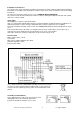
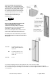
General assembly of the wall elements
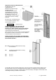
Figure shows a cross-section through a wall
section with profile wood boarding on both sides.
All wall elements are equipped with a vapour
barrier and heat insulation. After assembly of
the sauna, the vapour barrier must always be
located directly behind the interior boarding.
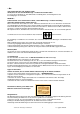
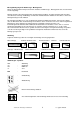
The inner side of the wall element is
indicated on the wooden frame by the
following stamp
innen .
inside = innen
Before erecting the individual elements, take
care to ensure that the groove side
(viewed from outside) is always on the left.
Mounting timber has been incorporated into the
wall elements for the bench mountings.
These are located approx. 39 cm and 83 cm above
the floor. The location of this timber can be seen
at the visible screw heads in the element frames.
Each time you install a wall element, ensure that
these screw heads are located in the lower half of
the element.
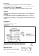
R1 + R4: for running cable from oven
control system module to the
sauna oven
R2: for running cable from oven
control system modul to the
control unit
R3 + R5: reserve
To prevent the dropping of the glass door, tighten the allen screw of the braces firmly.
The door fittings are to be checked when the cabin has been used repeatedly and adjusted if required.
The screws for fastening the door fittings and door handles are also to be tightened after the cabin has been
used repeatedly.