
Operating instructions

OPERATING INSTRUCTIONS FOR GAMBIT ADC2 24Bit / 192kHz A/D CONVERTER OPERATION
Daniel Weiss Engineering Ltd., Florastr. 42, CH-8610 Uster Page 9
+41 1 940 20 06 +41 1 940 22 14 http://www.weiss. ch weiss@weiss.ch
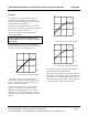
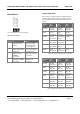
Dip Switches
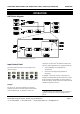
Fig. 9 Dip switches at the rear of the ADC2
DIP switch summary:
Switch up down
1 dual wire on XLR
outputs
single wire on XLR
outputs (both carry
the same signal)
2 dither setting affects
all outputs
dither setting affects
only RCA output
3 WSYNC input on
BNC NOT
terminated
WSYNC input on BNC
terminated
4 AES/EBU input NOT
terminated
AES/EBU input
terminated
AES OUT DUAL WIRE
If this switch is in the up position, the ADC2 outputs a
dual-wire signal. Refer to Table 2 and Table 3 to look
up exact output configurations depending on this dip
switch.
Sampling
Freq.
DO1
(XLR 1)
DO2
(XLR 2)
DO3
(RCA)
44.1 kHz 44.1 kHz
single wire
44.1kHz
single wire
44.1 kHz
single wire
48 kHz 48 kHz
single wire
48 kHz
single wire
48 kHz
single wire
88.2 kHz 44.1 kHz
left channel
44.1 kHz right
channel
muted
96 kHz 48 kHz
left channel
48 kHz
right channel
muted
176.4 kHz 88.2 kHz
left channel
88.2 kHz right
channel
muted
192 kHz 96 kHz
left channel
96 kHz
right channel
muted
Table 2 AES OUT dual WIRE switch in up position
Sampling
Freq.
DO1
(XLR 1)
DO2
(XLR 2)
DO3
(RCA)
44.1 kHz 44.1 kHz
single wire
44.1kHz
single wire
44.1 kHz
single wire
48 kHz 48 kHz
single wire
48 kHz
single wire
48 kHz
single wire
88.2 kHz 88.2 kHz
single wire
88.2 kHz
single wire
88.2 kHz
single wire
96 kHz 96 kHz
single wire
96 kHz single
wire
96 kHz
single wire
176.4 kHz 176.4 kHz
single wire
176.4 kHz
single wire
176.4 kHz
single wire
192 kHz 192 kHz
single wire
192 kHz
single wire
192 kHz
single wire
Table 3 AES OUT dual WIRE switch in down position
1: AES OUT 2 WIRE
2: DITHER MODE
3: WSYNC TERM.
4: AES IN TERM.