
Operating instructions

OPERATING INSTRUCTIONS FOR GAMBIT ADC2 24Bit / 192kHz A/D CONVERTER OPERATION
Daniel Weiss Engineering Ltd., Florastr. 42, CH-8610 Uster Page 6
+41 1 940 20 06 +41 1 940 22 14 http://www.weiss. ch weiss@weiss.ch
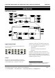
Threshold
If “threshold” is lit, the rotary knobs control the
threshold of the compressor section. The value is
shown in the numeric display. If “peak hold” is active,
the output peak value is displayed.
The ADC2 has a two-segment dynamics compressor.
The threshold can only be adjusted for the compressor
section, which has a fixed ratio of 2:1.
The limiter has a fixed ratio of ∞:1 with a fixed
threshold of 0.0 dBFS.
Because the signal before the output gain never
exceeds 0.0dBFS, the limiter is inactive if the output
gain is 0.0dB.
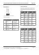
If the threshold is set to 0.0 and the output gain is
below 0.0 the dynamics section is inactive. This setup
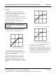
is shown in the input vs. output graph in Fig. 3.
Fig. 3 Compressor with 0.0dB Threshold
To activate the limiter, set the output gain to a
positive value. The boost will drive the signal into the
limiter. The gain reduction applied by the limiter is
visible on the yellow bargraphs.
To soften the transmission from linear to limiter
segment, the compressor can be activated by
adjusting the threshold parameter. Fig. 4 shows a
setting with a threshold of –3 dBFS, Fig. 5 shows –6
dBFS. The range of possible threshold values is listed
on p. 14.
Fig. 4 Compressor with -3.0dB Threshold
Fig. 5 Compressor with -6.0dB Threshold
The overall gain reduction applied by the compressor /
limiter is shown in the yellow bargraph.
Note that the compressor uses auto gain make-up:
depending on the threshold, a gain is added after the
compressor to ensure that 0.0 dBFS input results in 0.0
dBFS output (graphically speaking, auto gain make-up
“fixes” the transfer curve at the (0.0, 0.0) point).
0.0
-6.0
-12.0
+6.0
0.0
-6.0
-12.0
0.0
-6.0
-12.0
+6.0
0.0
-6.0
-12.0
0.0
-6.0
-12.0
+6.0
0.0
-6.0
-12.0