
Operating instructions

OPERATING INSTRUCTIONS FOR GAMBIT ADC2 24Bit / 192kHz A/D CONVERTER OPERATION
Daniel Weiss Engineering Ltd., Florastr. 42, CH-8610 Uster Page 10
+41 1 940 20 06 +41 1 940 22 14 http://www.weiss. ch weiss@weiss.ch
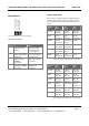
DITHER MODE
This switch determines how dither is applied to XLR
and RCA outputs. Refer to chapter POW-r Dither on p.
7 for further information.
WSYNC TERM.
If the “WORDSYNC in” is not connected to another
device (via a T-connector), this dip switch must be in
the down position, in which case the signal is properly
terminated.
If another unit is connected to the “WORDSYNC in”,
this dip switch must be in the up position.
Regardless of input synchronization type, the
“WORDSYNC out” always carries the word sync used
by the ADC2.
AES IN TERM.
If the loop-through output of the “DI 1 / SYNC” input is
not connected to another device, this dip switch must
be in the down position, in which case the line is
properly terminated.
If another unit is connected, this dip switch must be in
the up position.
FIREWIRE
If the optional Firewire Interface kit is installed, the
Firewire socket on the back of the unit becomes
active.
For the installation of the necessary driver software
refer to the installation instruction file on the driver
CD. The CD can be found on the last page of the
manual, or download the latest driver from:
http://www.weiss.ch/downloads/index.php
In the Weiss Firewire IO panel (the driver application)
the ADC2 device will be visible once the Firewire
connection has been established. The ADC2 becomes
the masterclock for the Firewire data transfers, i.e. the
Firewire interface will be automatically configured
such that it is slaved to the ADC2 output.
In the audio setup of your computer select the Weiss
Firewire Interface as the recording and/or playback
device.
The recording path uses the ADC2 XLR output as input
to the Firewire interface.
The playback path feeds the data coming into the
ADC2 via Firewire directly to the RCA output
connector. There are no ADC2 processing features
available for that path. I.e. it is possible to play a file
on the computer via the ADC2 firewire interface to
that RCA output. The RCA connector can be jumpered
in the ADC2 unit to carry either the Firewire output or
the standard ADC2 output as described in this manual.
If the ADC2 comes with the Firewire option installed,
the RCA connector is jumpered to the Firewire output.
Note that the ADC2 is the masterclock even when
using just the playback path. So make sure to set the
ADC2 to the sampling rate of the file to be played
back.
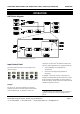
It is possible to connect more than one ADC2 to the
Firewire bus (use a Firewire hub or a computer with
more than one Firewire connector to establish such a
configuration). In such a case one of the ADC2 is the
masterclock for the whole system, i.e. the slave ADC2
unit(s) have to be synchronized to the master ADC2 via
e.g. the WORDSYNC (on BNC connectors) signal. In the
Weiss Firewire IO panel the master ADC2 unit is
selected (designated). All other ADC2 units on the
Firewire bus then are automatically configured as
slave units, i.e. their Firewire Interfaces are slaved to
the Firwire bus. Despite that slaving via the Firewire
bus, the aforementioned sync connections via
WORDSYNC (or AES/EBU sync) have to be established.
The slave ADC2 unit(s) have to be switched to external
sync via the appropriate frontpanel switches.