
User guide
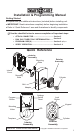
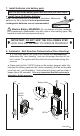

UP
KEEP
PARALLEL
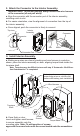
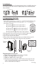
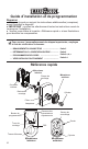
3.InstallExteriorAssembly.
Bolt
3
Wire
Harness
Adapter
For2-1/8”
diameteronly.
Fig.10
Fig.9
Fig.8
a. Placeadapterondoorasshown,
(note,adapterisnotrequiredif
mountingona1-1/2”(38mm)
diameterhole.
Crank
Torque
Blade
c. Placeassemblyondoor,threading
thewireharness(throughadapter-if
used)andunderthelatch.
b.Insertcylinderintoexterior
assembly.Withkeyincylinder,
rotatethetorquebladetoalign
withcrankinlatch.
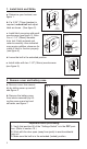
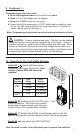
a. Carefullyinserttheconnectorofthewireharness-throughthecenter
holeofthemountingplate(seegure8).
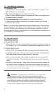
e.Checktheverticalalignmentformounting
plate and exteriorassembly.(Seegure10.)
h.Repeatasrequired.
f.Test.Usingthekey,retractandextendthe
boltafewtimestotestforsmoothaction.
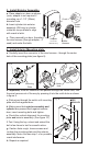
c. Slide wires through the notch until mounting
platesitsushagainstdoor.
4.InstallInteriorMountingplate.
Mounting
Plate
Connector
b.Important,oncetheconnectorhaspassedthroughthecenterhole,tuck
thewireharnessoutofthewaybypressingitintothenotchholeasshown
ingure9.
Notch
Hole
d. Making sure that exteriorassemblyand
cylinderarepressedushagainstexterior
door,insertmountingboltsandtighten.
g.Ifactionfeelsrough,loosenscrewsand
re-alignthemountingplateandtheexterior
assembly.Note:Alsoseestep1-cforpossible
crankinterference.