® Series 3 Oil-Fired Water Boiler Boiler Manual • Installation • Maintenance • Startup • Parts This manual must only be used by a qualified heating installer/service technician. Read all instructions, including this manual and all other information shipped with the boiler, before installing. Perform steps in the order given. Failure to comply could result in severe personal injury, death or substantial property damage.
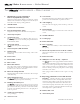
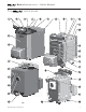
® Series 3 — Boiler Manual ® THE 1. WATER BOILER WATER BOILER – HOW IT WORKS . . . Weil-McLain logo plate (standard) or Remote Display Module (optional) The Remote Display Module (RDM) is used when the optional AFM (item 28) is installed. The display shows boiler and system status and is used to adjust operating parameters. 2. ON/OFF switch 3. Control Pod cover fastener 4. Pressure/Temperature gauge 19.
® Series 3 THE WATER BOILER — Boiler Manual ® Part number 550-142-182/1014 WATER BOILER 3
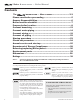
® Series 3 WATER BOILER — Boiler Manual Contents ® THE WATER BOILER — HOW IT WORKS............................ 2–3 Please read before proceeding ............................................. 5 Owners Responsibilities ........................................................ 6 Boiler location checklist ....................................................... 7 Prepare boiler location .......................................................... 8 Connect breeching ............................................
® Series 3 WATER BOILER — Boiler Manual Please read before proceeding Follow the guidelines below to prevent severe personal injury, death or substantial property damage. Fuel Do not start burner if: • • • Do not use crankcase drainings or any oil containing gasoline. See burner manual for proper fuel oil. Never burn garbage or paper in the boiler. Never leave combustible material around boiler.
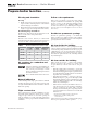
® Series 3 WATER BOILER — Boiler Manual Homeowner responsibilities— read and follow completely. 1. 2. Have the boiler and burner installed by a qualified installer. Have the boiler and burner serviced at least annually by a qualified service technician. Review and understand boiler start-up and routine maintenance procedures with the service technician. Perform routine maintenance listed below. 3. 4.
® Series 3 WATER BOILER — Boiler Manual Boiler location checklist Before placing the boiler, verify: United States installations must comply with all applicable U. S. codes: • Applicable state, local and national codes. • National Electrical Code. • Standard for Controls and Safety Devices for Automatically Fired Boilers, ANSI/ ASME CSD-1, when required.
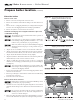
® Series 3 WATER BOILER — Boiler Manual Prepare boiler location Provide minimum clearances From combustible materials (see Figure 1) 1. Hot water pipes Figure 1 Minimum clearances to combustible surfaces and recommended minimum service clearances • All directions — ½ inch. (not shown in Figure 1) 2. Double-wall vent pipe • All directions — 6 inches. 3. Single-wall vent pipe. • All directions — 18 inches. 4. Boiler jacket surfaces • Top of Control Pod cover — 12 inches. • Sides and back — 2 inches.
® Series 3 WATER BOILER — Boiler Manual Prepare boiler location (continued) Flooring and foundation Follow code requirements Flooring 1. Install on any level, properly-supported, and noncarpeted surface. Flooring may be combustible if boiler leveling legs are installed. 2. Ensure the flooring is capable of handling the boiler weight (see page 39 for weight and water volume). Follow state, provincial or local codes when sizing adequate combustion and ventilation air openings.
® Series 3 WATER BOILER — Boiler Manual Prepare boiler location (continued) Place the boiler: Remove outer crate 1. Remove outer crate, leaving boiler on the crate base. 2. Remove the circulator and barometric damper cartons from the crate base. 3. Remove the two (2) shipping channels by loosening and removing the four nuts. Save the shipping channels for leveling leg installation. 4 . Remove the jacket cross tie fastened to the crate base.
® Series 3 WATER BOILER — Boiler Manual Prepare boiler location (continued) Perform hydrostatic pressure test: Figure 4 Burner door hinge installation See pages 2 and 3 for boiler feature locations. 1. Install air vent in relief valve tapping. 2. Plug supply and return tappings. 3. Install the boiler drain valve shipped with boiler. 4. Fill boiler. 5. Vent all air. 6. Pressure test boiler at 1½ times working pressure. Do not leave boiler unattended.
® Series 3 WATER BOILER — Boiler Manual Prepare boiler location (continued) Install the burner 1. Secure the burner flange to the burner door using the three (3) bolts provided. 2. Check for secure placement of insulation and sealing rope on the burner door. 3. Close the burner door and secure in place with the burner door screws and washers. 4. Follow the burner manual and boiler manual (pages 19 to 22) to wire the burner and connect fuel lines.
® Series 3 WATER BOILER — Boiler Manual Connect breeching (continued) Chimney venting (continued) Connect breeching: Long horizontal breechings, excessive number of tees and elbows or other obstructions restricting combustion gas flow can result in possibility of condensation, flue gas leakage and carbon monoxide emissions, which can lead to severe personal injury or death. 1. Connect full-sized breeching when possible. See Table 2, page 12, and Figure 5, below. 2.
® Series 3 WATER BOILER — Boiler Manual Connect water piping General piping information: ASME or Canadian requirements • If installation is to comply with ASME or Canadian requirements, an additional high temperature limit is needed. Install control in supply piping between boiler and isolation valve. Set control to a minimum of 20 °F above set point of the boiler limit temperature sensor. Maximum allowable set point is 220 °F. Wire control as shown on wiring diagram (page 20 & 21).
® Series 3 WATER BOILER — Boiler Manual Connect water piping (continued) DIAPHRAGM expansion tank (Figure 6) • Make sure expansion tank size will handle boiler and system water volume and temperature. Tank must be located near boiler before inlet to circulator. See tank manufacturer’s instructions for details.
® Series 3 WATER BOILER — Boiler Manual Connect water piping (continued) Piping MULTIPLE ZONES — System temperature 140 °F or higher 1. Follow instructions on page 14 and 15 to install piping near boiler. 2. Zoning with circulators (Figure 8) d. Separate relay is required for each circulator. 3. Zoning with zone valves (Figure 9) a. Install balancing valves to adjust flow to distribute heat to all zones. b. Separate transformer is required to power zone valves.
® Series 3 WATER BOILER — Boiler Manual Connect water piping (continued) Piping MULTIPLE ZONES — System temperature below 140 °F 1. If system water temperature requirements are less than 140 °F, such as radiant panels or converted gravity systems, use piping as shown in Figure 10 or 11. 2. If system piping is plastic without an oxygen barrier, a heat exchanger must be used. 3. Follow instructions on page 14 and 15 to install near-boiler piping. 4. Zoning with circulators (Figure 10) 5.
® Series 3 WATER BOILER — Boiler Manual Connect water piping Connect wiring (continued) Piping boiler in refrigeration systems (Figure 12) • • Install boiler so that chilled medium is piped in parallel with heating boiler. Use appropriate valves to prevent chilled medium from entering boiler. Consult AHRI Installation and Piping Guides.
® Series 3 WATER BOILER — Boiler Manual Connect wiring • Remove the Control Pod cover to facilitate wire routing. (To remove, push the Control Pod cover to one side, and gently work the cover retainer hinge on the other side out of the jacket slot.) Figure 14 Burner harness routing 120-volt wiring Conduits • Connect each conduit supplying line-voltage wiring to or from the boiler to a conduit opening in the upper portion of the jacket rear panel.
® Series 3 WATER BOILER — Boiler Manual Connect wiring (continued) Figure 15 Boiler and burner wiring, standard equipment 20 This wiring diagram is for standard boiler equipment. For wiring with optional AFM, see AFM instructions.
® Series 3 WATER BOILER — Boiler Manual Connect wiring (continued) Part number 550-142-182/1014 21
® Series 3 WATER BOILER — Boiler Manual Connect oil piping Make swing joints so they will tighten as tank settles. Non-hardening pipe joint compounds should be used on all threads. General oil piping requirements: • Location and installation of oil tanks, oil piping and burners must follow: • NFPA 31, Standard for the Installation of Oil-Burning Equipment. • In Canada, CSA B139, Installation of Oil-Burning Equipment. • Local codes and regulations. • Information provided with burner and fuel pump.
® Series 3 WATER BOILER — Boiler Manual Startup procedure • • • • • Follow information below to prevent severe personal injury, death or substantial property damage: Do not use gasoline crankcase drainings or any oil containing gasoline. See burner manual for proper fuel oil. Do not attempt to start burner when excess oil has accumulated, when unit is full of vapor or when combustion chamber is very hot. Do not start burner unless breeching and burner mounting door are secured in place.
® Series 3 WATER BOILER — Boiler Manual Check-out procedure ❏ 1. Boiler and heat distribution units filled with water? ❏ 2. Automatic air vent, if used, opened one full turn? ❏ 3. Air purged from system? Piping checked for leaks? be operating and should go off when controls are tested. When controls are restored, burner should re-ignite. ❏ 9. Limit control set to system temperature requirements (max. 220 °F)? ❏ 4. Air purged from oil piping? Piping checked for leaks? ❏ 10.
® Series 3 WATER BOILER — Boiler Manual Annual service and start-up The boiler should be inspected and started annually, at the beginning of the heating season, only by a qualified service technician. In addition, the maintenance and care of the boiler designated in Table 4 must be performed to assure maximum boiler efficiency and reliability. See the following pages for detailed instructions. Failure to service and maintain the boiler and system could result in equipment failure.
® Series 3 WATER BOILER — Boiler Manual Annual service and start-up (continued) Follow the service and maintenance procedures given throughout this manual and in component literature shipped with the boiler. Failure to perform the service and maintenance could result in damage to the boiler or system. Failure to follow the directions in this manual and component literature could result in severe personal injury, death or substantial property damage.
® Series 3 WATER BOILER — Boiler Manual Annual service and start-up (continued) Check all piping for leaks Check expansion tank Eliminate all system or boiler leaks. Continual fresh make-up water will reduce boiler life. Minerals can build up in sections, reducing heat transfer, overheating heat exchanger, and causing heat exchanger failure. Leaking water may also cause severe property damage. 1. Inspect all water and oil piping and verify to be leak free. 2.
® Series 3 WATER BOILER — Boiler Manual Annual service and start-up (continued) Check boiler relief valve 1. Inspect the relief valve and lift the lever to verify flow as in the following warnings, excerpted from a relief valve manufacturer’s warning label. Before operating any relief valve, ensure that it is piped with its discharge in a safe area to avoid severe scald potential. Read page 14 regarding relief valves before proceeding further.
® Series 3 WATER BOILER — Boiler Manual Annual service and start-up (continued) Clean boiler flueways and check refractory linings Figure 17 Access to boiler flueways Make sure all electrical connections to boiler are turned off and wait until boiler is warm, not hot, before cleaning. Failure to do so will result in severe personal injury, death or substantial property damage. Flue baffles The boiler contains fiberglass and ceramic fiber materials.
® Series 3 WATER BOILER — Boiler Manual Removing/replacing boiler jacket Removing the boiler jacket Figure 18 Jacket components and hardware Electrical shock hazard — The following procedure assumes the boiler has not been wired. If the boiler has been wired, you must disconnect all power to the boiler. Then label all wires before disconnecting them at the boiler terminal strip. The boiler contains fiberglass and ceramic fiber materials.
® Series 3 WATER BOILER — Boiler Manual Removing/replacing boiler jacket (cont.) 9. Push the Control Pod cover to one side, and gently work the cover retainer hinge on the other side out of the jacket slot to remove the cover. 10. Remove the limit temperature sensor and P/T gauge capillary from the wells in top of the boiler back section. 11. Remove the jacket cross tie by loosening the two screws securing it to the side panels (Figure 19).
® Series 3 WATER BOILER — Boiler Manual Replacement parts (continued) Boiler section assembly parts Item Description 1 Boiler front section 316-900-200 2 Boiler intermediate section 316-900-210 3 Boiler back section 316-900-220 4 Tie rods (4 required) 5 Nuts (8 required) 561-928-221 6 Washers (4 required) 562-248-668 7 P/T gauge temperature sensor well 592-300-025 8 Limit control LWCO sensor well 592-300-026 9 Mounting clip for P/T gauge and limit well 512-400-001 10 P/T gau
® Series 3 WATER BOILER — Boiler Manual Replacement parts (continued) Boiler section assembly parts Part number 550-142-182/1014 33
® Series 3 WATER BOILER — Boiler Manual Replacement parts (continued) Burner door parts Item 34 Description Part Number 1 Burner flange bolts (3) each, 5/16”-18 x 3/4” Hex head Stainless Steel Purchase locally 2 Burner door 330-054-308 3 Burner door hinge bracket 466-900-000 4 Hinge bracket screws (2 required), 3/8”-16 x 1 5 Observation port assembly (includes observation port, bolt, observation port gasket, sight glass gasket, sight glass, & water glass) 386-902-000 6 Observation por
® Series 3 WATER BOILER — Boiler Manual Replacement parts (continued) Burner door parts Part number 550-142-182/1014 35
® Series 3 WATER BOILER — Boiler Manual Replacement parts (continued) Jacket and control parts Item 36 Description Part Number 1 Jacket front panel assembly (includes sheet metal, plastic, & striker) 386-902-005 2 Jacket front panel plastic 595-000-009 3 Jacket side panel (left and right sides are the same) 4 Control pod cover 5 Jacket top panel 6 Jacket rear panel (if required order insulation below) 426-900-001 7 Jacket rear panel insulation 591-222-181 8 Jacket cross-tie 426-9
® Series 3 WATER BOILER — Boiler Manual Replacement parts (continued) Jacket and control parts Part number 550-142-182/1014 37
® Series 3 WATER BOILER — Boiler Manual Dimensions Notes 1. Boiler circulator is shipped loose. Circulator may be mounted on either boiler supply or return piping. 2. Relief valve is shipped loose, supplied with elbow and nipple to install in rear section tapping.
® Series 3 WATER BOILER — Boiler Manual Ratings DOE ® AHRI Certified Ratings Boiler Model Number Flue Conn. Size Shipping Weight, Approx. Draft Loss Through Boiler Gallons Inches Pounds Inches w.c. Heating Capacity Seasonal Efficiency MBH AFUE % MBH Notes 1, 6 Notes 2, 6 Notes 3,6 112 98 87 86 15.0 6” 636 0.000 Burner Input GPH Boiler Water Content Net Rating (water) MBH Notes 2, 6, Note 4 Note 5 UO-3RE 0.80 Note 7 Note 7 UO-3E 1.00 140 123 87 107 15.
® Series 3 40 40 WATER BOILER — Boiler Manual